

For the first eight years we owned Nine of Cups, our 1986 Liberty cutter, I seemed to be forever chasing air leaks in the diesel engine fuel system. The engine would run flawlessly for a few months, then some minute air leak in the system would cause it to sputter and die after a few hours of operation, invariably at the worst possible moment. I would tighten or replace every clamp and fitting, change any suspect fuel hose and eventually cure the problem – for a few months anyway. The problem cropped up again a few years ago on a long offshore passage from Ecuador to Chile, as we headed for Puerto Montt and the fiords of Patagonia. This area is known for its many hazards, fickle winds and strong currents, and a reliable engine is essential. To resolve the problem temporarily, I built an emergency day tank to get us by, but resolved to build a permanent gravity feed day tank as soon as I could.
A day tank has much to be said for it. It sits higher than the engine, and as the name suggests, uses gravity to supply fuel to the engine. Any leaks in the fuel line downstream of the day tank tend to leak fuel out rather than draw air in, making them easy to locate. Any air bubbles in the system between the fuel tank and day tank migrate upwards to the day tank and dissipate rather than being forced into the injector pump. For Nine of Cups, it seemed a perfect solution.
I first had to decide how to pump fuel into the day tank. The first option I considered was to use the engine lift pump. There are two drawbacks to this approach. Since it would run continuously whenever the engine was running and cannot be shut off when the day tank is full, I would have to add a return fuel line to prevent the day tank from overflowing. The return line could be teed into the engine fuel return line, but this hose would then have to be replaced with a larger diameter hose. The biggest problem with this approach, however, is that I would have to use the lever on the lift pump to manually transfer fuel to the day tank whenever it was empty or low. Transferring that much fuel would be a long slow process.
The second option I considered was to use an electric fuel pump to refill the day tank. I could control it with a simple switch for manual operation. I also felt confident I could construct a simple, low cost controller that would turn the pump on when the tank was low and turn the pump back off when the tank was full. I decided this was the best option, and Figure 1 shows a block diagram of the system.

Figure 1. Fuel system block diagram
To build the day tank, I decided to use 1/2” plywood coated and reinforced with epoxy. Thinner plywood, 3/8” or even 1/4” would have been strong enough, but I chose 1/2” so that the wall would be thick enough to bond studs in place for holding the top on. I use West System epoxy for most of my projects, and their website includes a paper1 that I found to be very helpful. It specifically addresses the steps that should be taken when constructing wood/epoxy composite tanks for diesel fuel. If using epoxy other than West System, you will want to contact the manufacturer for their suggestions.
I took some rough measurements in the engine room to determine the approximate size for the tank. I made our tank 10” wide by 8 “ deep by 13.5” high. This holds a calculated value of about 4.5 gallons. I decided to build a shelf above the engine to set the tank on, and hold it in place with straps. That way, I could easily remove it in the future if and when I needed to clean the tank interior, make repairs, etc. Figure 2 shows the design plan for the tank.
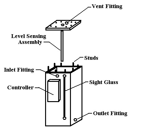
Figure 2 – Design drawing for the day tank
Using exterior grade plywood, I cut the five pieces of wood to make the sides and bottom of the tank, glued them all together, then cut a separate piece to be used as the top. I wanted to be able to remove the top, so I drilled holes vertically down into the sides of the tank, and using epoxy, bonded hex head machine screws into the drilled holes. By drilling matching holes in the top, I would be able to hold it in place with washers and nuts.
I used a thickened epoxy compound to add fillets to all the interior corners of the box, then I laminated a layer of biaxial fabric with mat to the inside surfaces of the box and the top. I then drilled all the holes necessary for the fittings and sight glass. For the controller described later in this article, I drilled a hole in the center of the top that was about 1/16” larger than the 1/2” PVC pipe used for the sensors. Then I applied two coats of epoxy to the exterior surfaces and six coats to the interior surfaces and edges, including the holes for the fittings. West System recommends a slightly resin rich ratio of resin to hardener when coating the inside of a tank. Table 1 shows the suggested ratios of resin to hardener using the West System pumps.

Table 1. dispensing guidelines using pumps
Once the epoxy cures, West System also recommends doing a post cure period of 4-8 hours at an elevated temperature of 120 degrees F. I suspended a 60 watt incandescent light into the tank, positioned the top in place and left it overnight.
The next step in the construction of the tank is to thoroughly scrub the inside and outside of the tank and top with water and an abrasive pad to remove any surface contamination and the amine blush that usually forms on the surface of epoxy as it cures. I scrubbed it twice, then dried it with paper towels. Then I painted the exterior of the tank. I sanded the surface of the epoxy, applied a coat of primer, and two coats of enamel paint. I used red, for no reason other than it matched the color of my Ford engine.
Next I attached the fittings for the hoses and sight glass. I used brass fittings with barbed hose connections on one side and female NPT connections on the other. I used short threaded nipples that screwed into the NPT connections and that were long enough to pass through the wall of the tank. These were held in place and sealed on the inside of the tank with a gasket, flat washer and nut. Figure 3 shows the details of each connection. For the sight glass, I used 1/4” right angle barb fittings and a section of clear plastic hose. I wasn't sure how long the clear hose would last or remain clear enough to view the fuel level, but after two years it shows no sign of deterioration. It is easy to replace if necessary.
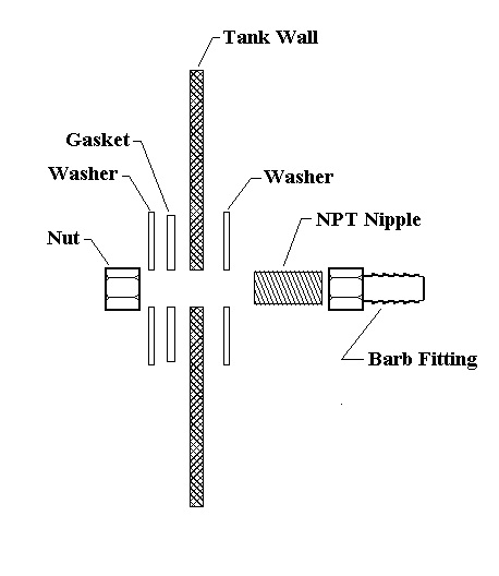
Figure 3. Hose fitting details
The temporary day tank I had initially built had a very simple controller for refilling the tank - an egg timer. When we were running the engine, we would set the egg timer to 45 minutes, and when it went off, one of us would go below, flip the switch to the electric fuel pump, watch it for 5 minutes or so until the tank refilled, switch the pump off and then reset the timer. Ninety five per cent of the time, this routine worked flawlessly, but every once in awhile something would go awry and the engine would sputter and die or fuel would overflow the tank. Typically, instead of sitting there watching the fuel go into the tank for 5 minutes, I would do something else like start heating water for a cup of coffee, go to the head, or some other simple task, and then sometimes forget that the tank was filling. When the tank overflowed, fuel would run along the shelf, down the engine room wall and out under the port engine room door onto the galley floor. As I poured my cup of coffee and noticed I was standing in a pool of diesel, I would be reminded that I might have left the pump on a bit too long. Just as often, one of us would forget to restart the timer or, on occasion, the timer would stop ticking and go unnoticed, and the engine would run out of fuel. For the permanent day tank, I wanted an automatic controller.
To sense the level of the fuel in the tank, I used four reed switches. These are tiny glass encased switches that are activated by bringing a magnet in close proximity to them. The plan was to use a float of some sort with a magnet attached that would slide up and down on a PVC pipe. The reed switches would be inside the PVC pipe, and as the magnet attached to the float came near each switch, the contacts of the switch would close. Two of the reed switches would signal the point at which the fuel pump should be turned on and off. The third reed switch would indicate a low fuel level in the tank. By sounding an alarm, we would get a few minutes warning before the engine died if the pump failed, the main tank had run dry or the primary fuel filter was clogged.
Anytime the day tank was low or empty, there should be a way of turning the pump on manually. To do this, I wanted to control the fuel pump with a switch much like a bilge pump switch, with positions for On, Off, and Automatic. Since it would be possible (and, actually, quite likely with my short attention span) to put the switch in the On position and forget to switch it back to Automatic mode when it refilled, the fourth switch would indicate a high fuel level in the tank and sound an alarm.
My next decision was what to use as a float. It needed to be impervious to diesel and light enough to float. I considered carving a doughnut out of foam and encapsulating it in epoxy. Though this would have worked, I discovered that the float from a carburetor rebuild kit for my outboard was the perfect size to slide up and down on a length of 1/2” PVC pipe, and this is what I used. I epoxied two magnets onto opposite sides of the top of the float.
To build the sensor assembly, I started with a length of ½” PVC pipe that was about 1-1/2” longer than the inside height of the tank. I bonded a cap onto the bottom of the pipe. I wanted to permanently attach the pipe to the top of the tank, and to do this, I took two more PVC caps and cut the ends off, leaving two rings that could be slid onto the pipe. I then made two circular gaskets from a diesel impervious gasket material (O-rings would also work) to make a watertight seal. I positioned the pipe so that it would clear the bottom of the tank by about 1/2” when the top was screwed down, then marked the pipe where it exited the top of the tank. Next I slid the float onto the pipe and used PVC adhesive to bond the lower ring in place. I slid one of the gaskets in place, positioned the PVC pipe in the hole, slid the top gasket in place and then glued the top ring into place, making sure to apply enough pressure to slightly compress the gaskets.
The next step in making the sensor assembly was to mount the reed switches. I planned to attach each reed switch to a dowel, and slide the dowel into the PVC pipe. I found a dowel of the correct diameter, cut it the same length as the PVC pipe, and began marking the location that each switch would be positioned. The lowest switch would be the Low Fuel sensor and I marked the dowel even with the magnet when the float was resting on the cap at the bottom of the PVC pipe. The highest switch would be the High Fuel sensor, and I marked the dowel even with the magnet when the float was moved up as high as it would go. The next switch would turn the fuel pump on, and for this sensor I put a mark on the dowel about ¼ of the distance between the Low and High Fuel sensor positions. The last switch would turn the fuel pump off, and I put a mark on the dowel about ¾ of the distance between the Low and High fuel sensors.
Next I soldered the two wires onto each reed switch. Since the current passing through each switch will be small, I used AWG 28 wire, but any size between AWG18 to AWG 28 will work. The wires must be long enough to connect each switch to the controller . I planned to mount the controller onto the day tank, so I allowed about 2 feet of wire to reach from the PVC pipe to the controller. I used masking tape to label each pair of wires as “Lo”, “On”, “Off” and “Hi”, and then used a hot glue gun to attach each switch to the dowel. I secured the wires to the dowel with cable ties and slid the dowel into the PVC pipe. Using an Ohmmeter connected to each pair of wires, I slid the float up and down the PVC pipe to make sure all sensors were working. The completed sensor assembly is shown in Figure 4.
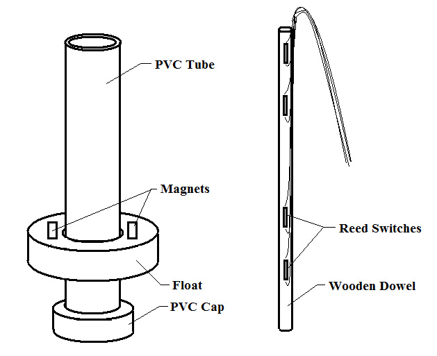
Figure 4 – Sensor Assembly
I wanted the controller circuitry to be simple and reliable, and chose to use 4 relays as the basic control elements. The schematic in Figure 5 shows the basics of the controller. It consists of the four reed switches, four relays and an alarm horn. When the magnet passes close to any of the sensor switches, the contacts close – otherwise the switch contacts are open. Three of the relays have one set of contacts. When the relay coil is not energized, the Normally Closed or NC contacts are closed. When the coil is energized, the Normally Open or NO contacts are connected. The fourth relay, labeled “Fuel On”, has two sets of contacts that function in the same manner.
To understand how the circuit works, lets assume there is enough fuel in the day tank to position the float somewhere between the “Fuel On” and “Fuel Off” sensors. Since the magnet is not close to any of the sensor switches, all four of them are in the open position, and all the relays are in the de-energized or NC positions. As the fuel is consumed, the float drops lower until the magnet comes into proximity with the “Fuel On” sensor and the switch contacts close. This routes 12 volts to the coil of Relay 1, energizing it and causing the center contacts to connect with the NO contacts. If you follow the wire from the plus side of the pump, you can see it goes to the upper set of NO contacts of Relay 1, then to the NC contacts of of the “Hi Fuel” relay, to the NC contacts of the “Lo Fuel” relay and then to 12 volts. As long as the “Fuel On” relay is energized and neither the “Lo Fuel” or “Hi Fuel” sensors are activated, the pump will run.
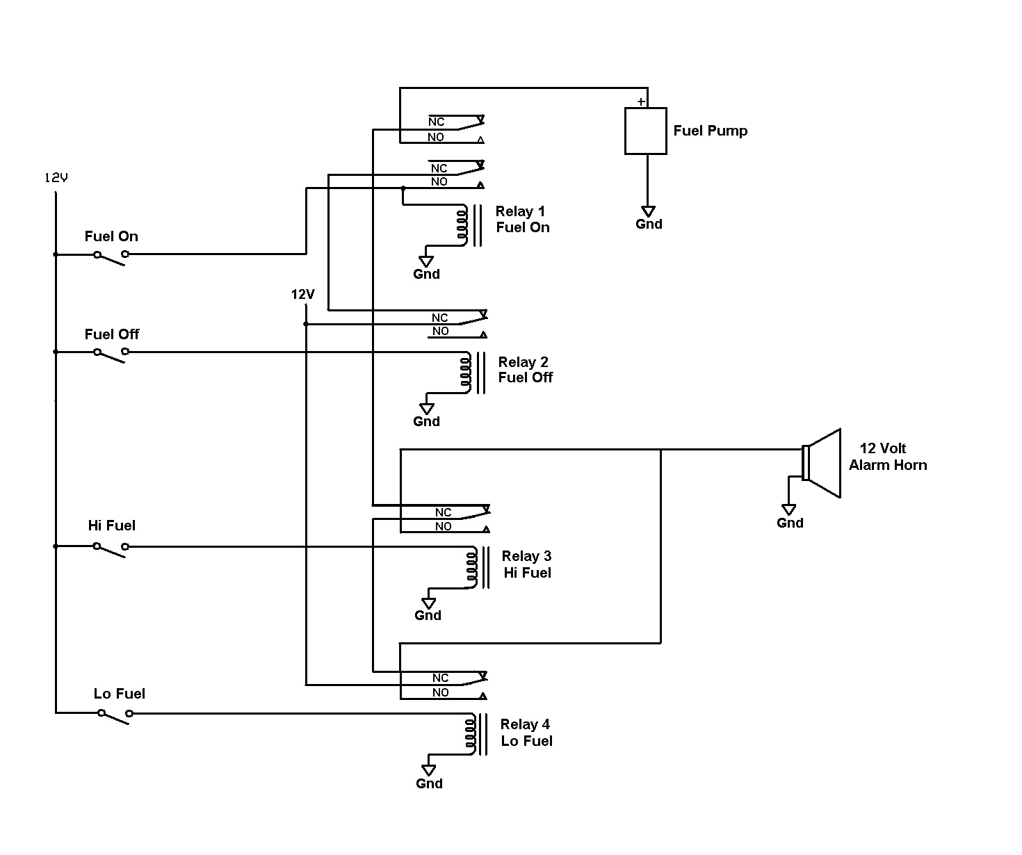
Figure 5. Basic Controller Schematic
As fuel is pumped into the day tank, the float will begin to rise again and the “Fuel On” sensor switch contacts will open. Relay 1 remains energized, however, because 12 volts is still routed to the coil through the NC contacts of Relay 2 and the NO contacts of Relay 1. The pump remains on until the float reaches the “Pump Off” sensor, energizing Relay 2, and turning the pump off. As fuel is consumed again, the float begins to drop, Relay 2 is de-energized, and the process starts over.
If, when the float drops down to activate the “Fuel On” sensor, something prevents the tank from filling, such as an empty main fuel tank for example, the float will continue to drop lower until the “Low Fuel” switch contact closes. The “Low Fuel” relay will be energized, and the pump will be turned off. In addition, 12 volts will be routed to the alarm horn through the NC contacts of the “Low Fuel” relay. Likewise, if the fuel continues to be pumped into the day tank after the “Fuel Off” reed switch is activated, once the float reaches the “Hi Fuel” sensor, the pump will be shut off and the alarm horn will sound.
I wanted a few refinements to complete the circuit. When the horn is sounding, I want some indication of what is causing the alarm. In addition, I want to be able to turn the horn off while I correct the problem. I added two red LEDs to indicate the “Hi Fuel” or “Low Fuel” conditions, and a switch to turn the horn off. I also added a green LED to indicate that the pump is on. Finally, I added connectors so that the controller could be disconnected and removed if desired, and a switch for the pump with On, Off and Automatic positions. The complete schematic is shown in Figure 6.

Figure 6. complete controller schematic
Note that there are two minor shortcoming to the controller design that could be corrected at the cost of added complexity. First, if the pump switch is in the “ON” position and the engine ignition is off, there will be no alarm if the tank overflows. Second, if the alarm is sounding, I have to look in the engine room to determine the cause. It would be nice to add external LEDs for the Day Tank status.
For the fuel pump, I went to a local auto parts store and asked for a universal diesel compatible electric fuel pump. For my 90HP Lehman, even the smallest fuel pump at 30 gallons per hour was considerably more than I needed. The least expensive price I found was $38.00, and this included a mounting bracket and hose fittings.
Building the circuit is straightforward if you have done any electrical soldering. If not, the Nine of Cups website given in the appendix has a tutorial on building “Homebrew circuitry” as well as the tools and supplies needed. A complete parts list is provided in the appendix. The circuit board was mounted in an enclosure with the LED indicators on the front. I located the switch in the engine room in an accessible position. The photo below shows the completed day tank with controller attached.
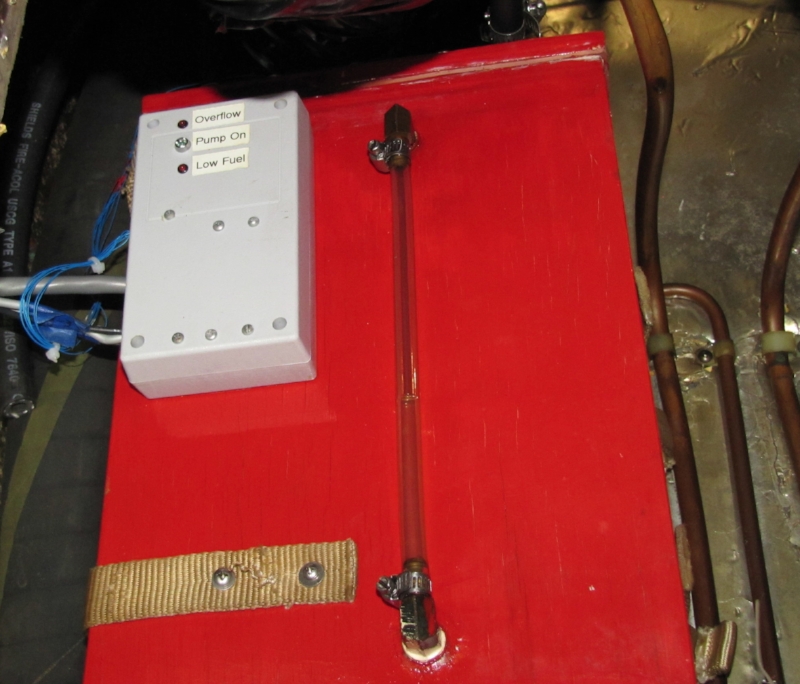
Completed Day tank
Once the controller was completed and tested, the top was screwed in place, and the hoses were all attached. The fuel pump was turned on until the day tank was half full, then the switch was set to automatic. It worked flawlessly, and has continued to work without a problem for over two years now. We have been completely happy with it, and it has totally eliminated our air leak problems. The total calculated capacity is about 4.5 gallons, but the amount of fuel that is pumped each cycle is closer to 2 gallons, enough for 1-3 hours of motoring depending on speed.
References:
“Building Tanks with West System Epoxy - Wood/epoxy composite tank guidelines”, Patrick Ropp, http://www.epoxyworks.com/18/pdf/tanks.pdf
Tutorial on Constructing Onboard Electrical Projects, www.nineofcups.com/...TBA
Jameco Electronics, www.jameco.com, (800) 831-4242
Defender Industries, www.defender.com, (800) 628-8225
