

When we were in Patagonia a few years back, we tied up at a marina in Puerto Montt for several weeks. We dug out our power cables and the appropriate connectors and adapters, and connected to shore power at the nearest power box. All was good for awhile, but every few hours the Ground Fault Circuit Interrupter (GFCI) breaker would trip, and Nine of Cups, as well as the three other boats connected to the circuit would lose power. This was quite annoying, and when we mentioned it to the marina manager, he called an electrician in to investigate. We were very embarrassed to learn it was our 5-year-old power cable that was the cause of the problem.
Unless the insulation has completely broken down, the insulation resistance of a power cable cannot be checked with an ordinary multimeter. Most multimeters check resistance by applying only a few volts, and a much higher voltage is necessary to see any measurable leakage. Instead, a megohmmeter is used to measure the quality of the insulation in a cable.

Typical megohmmeters
A typical megohmmeter differs from a multimeter in the ohmmeter mode in three ways. First, it applies a much higher voltage – typically 500vdc to 1000vdc. Second, it measures resistance in megohms – a megohmmeter can typically measure up to 2000 megohms vs 1 megohm with a multimeter. Third, the output of the megohm has a high internal resistance, making it less hazardous to use despite the high voltages present.
Not that long ago, a megohmmeter was the size of tool box and cost several hundred dollars. Now, a basic tester for checking insulation is the size of a handheld multimeter and can be purchased for under $75. If the budget will allow, it is a handy device to have aboard.
proof test
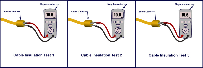
The simplest test for checking the insulation of a marine power cable is called a “Proof Test” as shown in Illustration 1. Disconnect both ends of the cable, and connect the black test lead between the common terminal of the meter and the ground wire of the cable. Connect the red test lead between the Volts/Ohm terminal of the meter and one of the power conductors. Select the 1000v setting, then press the test button for several seconds. It may take a second or two for the resistance reading to stabilize. Repeat the test between the second power conductor and ground, and again between the two power conductors. In all configurations, the resistance between any two conductors should be higher than 1 megohm. (Note: older or more sophisticated megohmmeters may use a different procedure for checking cable insulation – refer to the owner's manual.)

tool insulation test
Getting a little tingling feeling when using your power grinder? You might want to check its insulation before using it while standing in a puddle of water. Connect the megohmmeter between each power conductor and the ground conductor. Double-insulated tools have only two prongs in the power cord, and in this case, connect the tester between each of the power conductors and any exposed metal on the tool as shown in Illustration 2. There should be at least 1 megohm between ground and either of the power conductors. (Note: the resistance between the two power conductors will be low – a few hundred ohms or less – which is normal).
The megohmmeter can also be utilized to check the insulation of the windings of motors and alternators. For an alternator or brushless DC motor, the stator windings should be disconnected from each other and the resistance checked between windings and between the windings and ground. For brush type DC motors or generators, the brushes should be removed and the resistance checked between the coils separately. For a 12 volt motor or alternator, all resistances should be a minimum of 100k ohms.
Many boats incorporate transformers on the incoming shore power, either to provide isolation from shore AC or as a step-up or step-down transformer to convert 220VAC to 120VAC or vice versa. We have a 1 kVA step-down transformer aboard Nine of Cups. The megohmmeter can be used to check the insulation of the windings. The transformer should be disconnected from shore power and onboard circuits, and the resistance of each winding checked against the other and to ground. For a typical 120VAC isolation transformer, all resistances should be in excess of 350 megohm. For a step-down, step-up, or 220VAC isolation transformer, the resistances should be greater than 650 megohms.
While a megohmmeter may not be an essential tool to have aboard, it is certainly a useful one. Now that they have become reasonably priced, it may make sense to buy one.