

Blue View - Master Electrician Exam
/What I know about AC electrical circuitry, however, was what I learned along the way on the boat and in the various houses we've lived in.
Read MoreWhat I know about AC electrical circuitry, however, was what I learned along the way on the boat and in the various houses we've lived in.
Read MoreSooner or later, if you own your boat any length of time, you will have to deal with replacing or adding a DC electrical circuit. Perhaps you are upgrading an older piece of gear and the wiring is corroded or inadequate, maybe you are adding some new electronics, or maybe you are replacing a previous owner's amateurish handiwork that is now causing problems. Whatever the reason, it is not difficult to do the job correctly, with results that are professional looking, safe and reliable.
 Planning the installation
If you are upgrading an older piece of electrical gear, you may only need to replace the old wiring with new. If the amperage requirements of the new gear is no more than the old, if it was wired correctly to begin with, and the circuit it is connected to is not overloaded, it should be fine. Otherwise, you will need to find a new circuit for your power connection. So how do you go about finding the best place to connect the new wiring?

Figure 1 shows a simplified DC electrical schematic for a typical sailboat. It has two house batteries in parallel and one starter battery. The switches allow either battery bank to be disconnected or to be re-routed. For example, if the starter battery died, it is an easy matter to start the engine using the house battery bank. The breaker panel has one sub-main breaker and several branch breakers, only a few of which are shown in the figure.
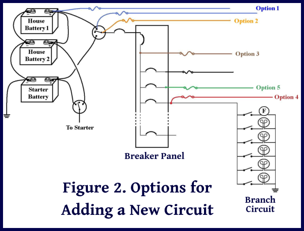
Figure 2 shows several options for connecting your new electrical gear to the house batteries. Option 1, shown in blue, connects the new circuit directly to the battery. This is allowable for certain equipment that should be powered all the time, such as battery chargers, safety equipment (bilge pumps, alarms, etc.), and electronic equipment requiring continuous power for its memory. As long as there is a fuse or circuit breaker in the circuit and it is placed no more than 7” (178mm) from the battery or the switch, this method is acceptable. ( Note: if the conductor is enclosed in a sheath or enclosure, the fuse can be located up to 72” (182cm) from the battery terminal or within 40” (102cm) of the switch.)
The second option is to connect the new circuit to the battery switch as shown in orange in Figure 2. This is acceptable, again, as long as the fuse is within 7” (178mm) of the switch, or within 40” (101cm) of the switch if the conductor is contained in a sheath or enclosure. This option is better than the first for most equipment because the circuit can be switched off using the battery switch.
In the third option, the brown wiring in Figure 2, the new circuit is connected downstream of a circuit breaker. Depending on the type of equipment being connected and the conductor size, a fuse may or may not be required.
You can also connect the new circuit to an existing branch circuit as shown in red in Figure 2, which in some cases, may be the best option. As in the third option, a fuse may or may not be necessary depending on what you are installing. If you are adding a new reading light to the starboard settee, it makes perfect sense to connect it to the “Stb Cabin Lights” breaker. On the other hand, it would be illogical to connect the wiring for a new chart plotter to that same branch circuit. Before deciding on this fourth option, you should calculate the existing load on the branch circuit and make sure the new equipment will not overload the circuit. If the existing load plus the amperage requirements of the new circuit are less than the breaker size, it is probably safe to add the new circuit. In some cases, it might be possible to increase the breaker size, but this is unwise without carefully evaluating the conductor sizes and loads in an existing branch circuit. (The last few blogs discussed the processes for calculating loads and wire sizes).
One other option for connecting the new circuit is the green wiring shown in Figure 2. If you have a spare breaker, the circuit can be wired as a new branch circuit. This would be the best option if you are installing some new gear like an autopilot, refrigeration unit, or radar. The fuse may not be necessary if the breaker is sized correctly.
The two key things to remember are:
Want to know how to install a fuse? Stay tuned to next week's blog.
It is usually quite simple to calculate the electrical load on a circuit. If there is only one electrical device connected to the circuit, the load is simply the amount of current the device consumes when it is running. If a circuit only powers an electric bilge pump, and the pump draws 8 amps, then this is the load. The wiring and fuse or breaker must be adequate to handle 8 amps.

If there are several devices connected to the circuit and all are often running simultaneously, then the total load can be calculated by adding up the current requirements of each device. For example, if we have an autopilot that requires 6 amps, a GPS that draws 2 amps, and a chartplotter that draws 3 amps, then the total load on the circuit would be 11 amps.
But what if we have a number of devices connected to a circuit, some of which may be on all the time and some of which are on only part of the time? Do we tally up the loads for every device and design the circuit to handle this worst case load? Do we take the average load? Maybe the average load plus a fudge factor? If we guess wrong in one direction, we will be popping breakers or blowing fuses on a regular basis. If we design the circuit for the worst case scenario, we will be spending a lot more on wiring and breakers than we probably need to.
Fortunately, the National Fire Protection Association (NFPA) as well as the American Boat and Yacht Council (ABYC) provide some guidance. The ABYC provides a worksheet developed for boats, and it is quite helpful in determining the likely total load on a circuit that has multiple devices. I've modified it slightly and show it below.

The two columns on the left side are for devices connected to the circuit that are on either continuously or for long periods of time. There are several blank lines provided, so if your boat has other devices on the circuit, add them in 'Column A'. Next enter the current required for each device in the 'Amps' column, and add these all up and enter the total in the cell labeled 'Total of Column A'.
The columns on the right are for devices that are only on occasionally. Again, add any additional devices in 'Column B' and then enter the current required for each device in the 'Amps' column. Add these all up and enter this total in the cell labeled 'Total of Column B'. Now multiply this by 0.1 and enter it in the following cell, '10% of Total of Column B (1)'.
Scan the 'Amps' column on the right side and find the largest single load. Enter this in the cell labeled 'Largest Single Item of Column B (2)'. (Not too difficult to follow so far, eh?). Enter the larger of the two values, either (1) or (2), in the applicable cell on the left side, and add it to the 'Total of Column A' cell. The resulting sum is the total load likely to be seen at any given time.
I find the process to be fairly straightforward, and much easier than, say, filling out a 1040 Tax Form.
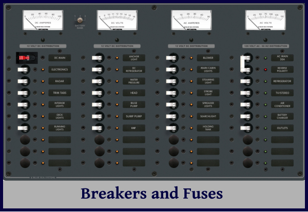
Next week, I'll talk about circuit breakers and fuses. Stay tuned.
Hi there and welcome to Just A Little Further!
We are David and Marcie Lynn and we've lived aboard our Liberty 458 cutter-rigged sailboat since 2000.
What began as an urge to travel slowly and economically at our own pace ended up an adventure of a lifetime.
Well, here we are ... nearly 90,000 miles under the keel, 5 continents, 5 Great Southern Capes, 36 countries and almost two decades later, still taking one passage at a time and going just a little further.