
Blue View – Auxiliary Switches
/An option that is available on Ford Transits is a panel of four auxiliary switches. We're not sure whether Blue's original parents ordered the van configured the way they wanted it or whether it was just purchased off the lot, but either way, Blue has the optional switches installed.
The output from each switch is fused at 20 amps, and all are fed to a harness and connector located under the driver's seat. They are only energized when the ignition is turned on, which makes them ideal if the plan is to add additional electrical circuits that can be controlled by switches in the cockpit when the engine is running. So far, I only have plans for one of the switches – controlling the right sideview camera that will hopefully give us a little better visibility when we're trying to back out of a parking space.
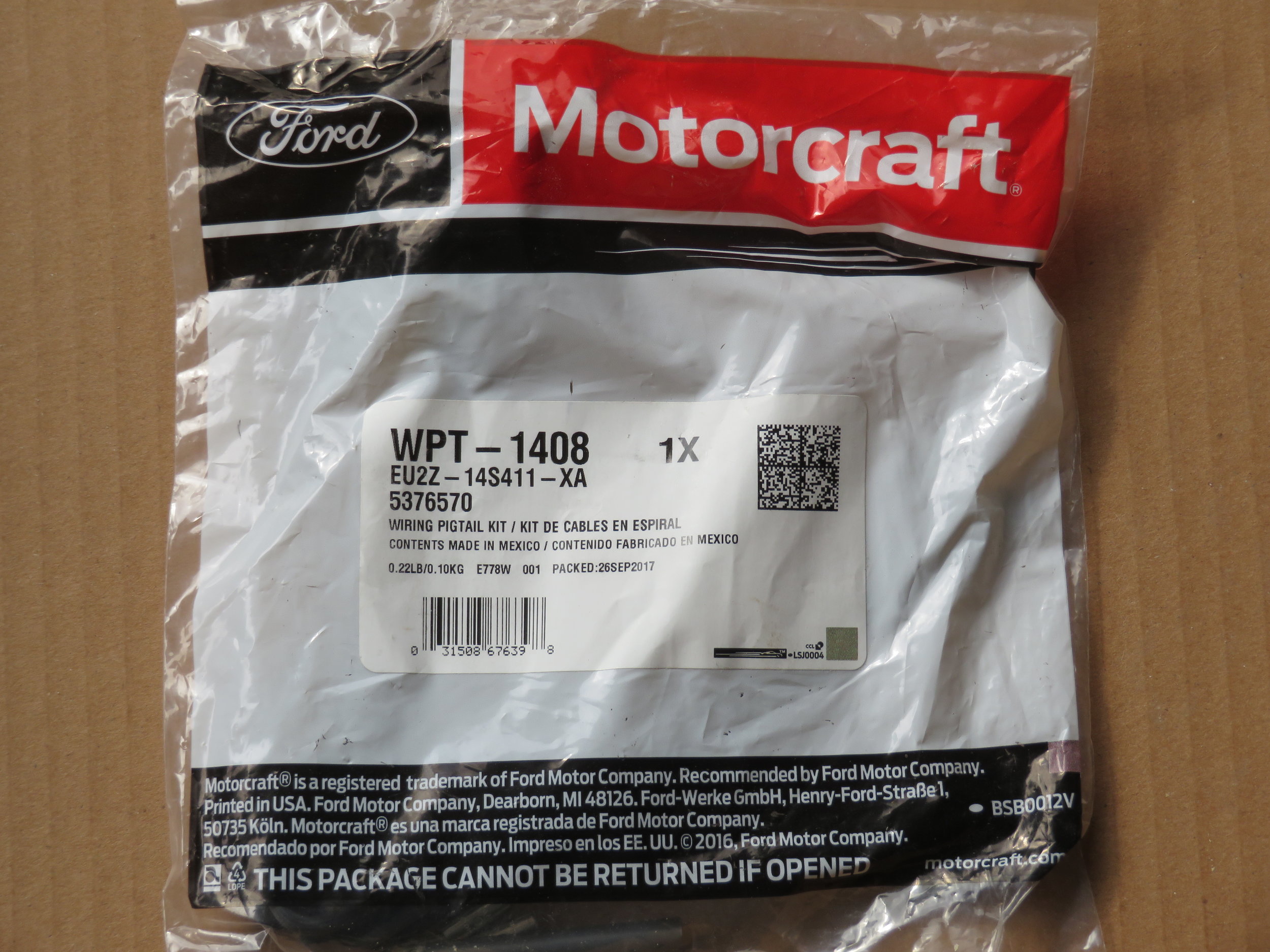
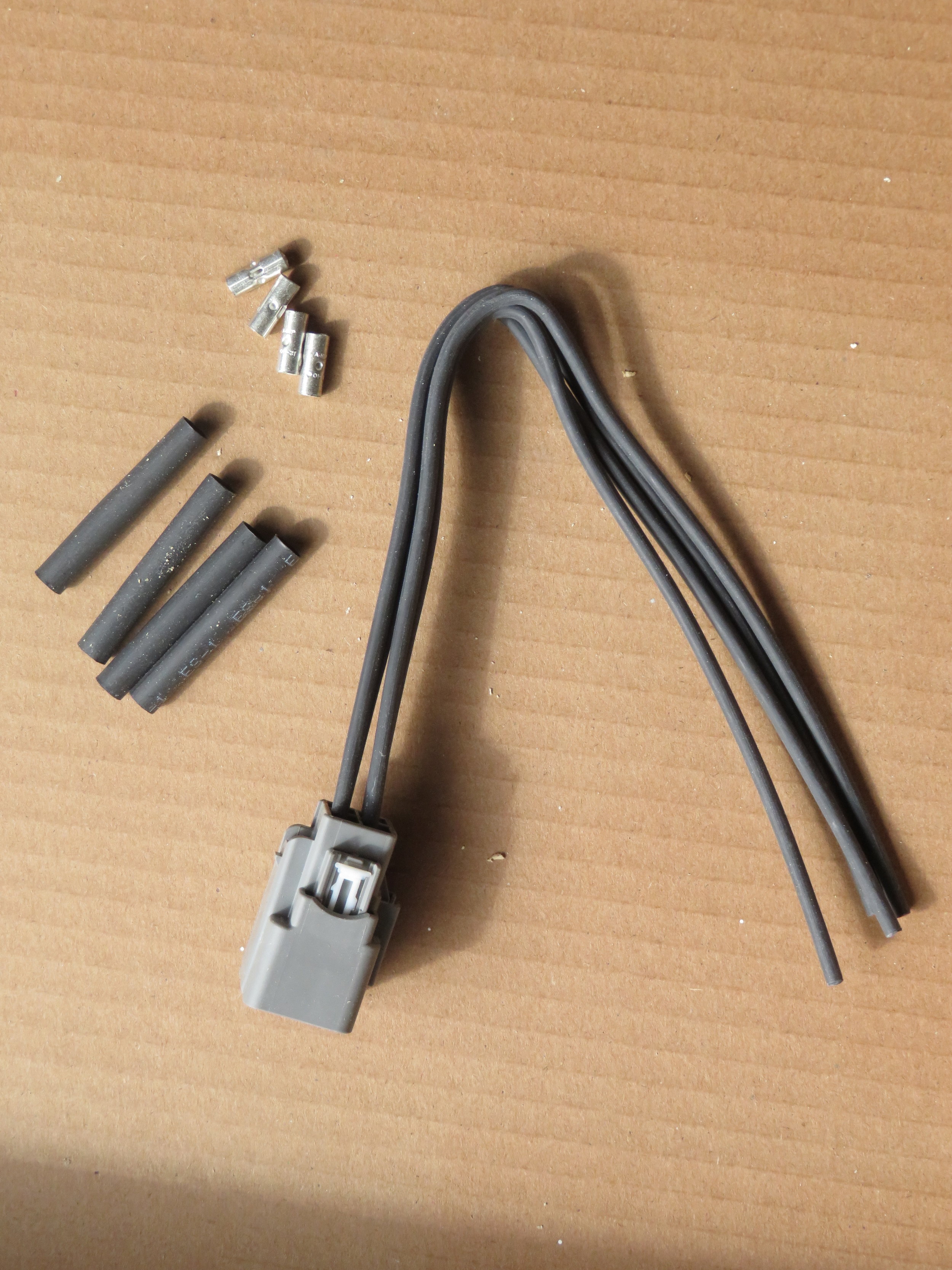
The connector for the switches has four blade-type terminals, and it is possible to make a connecting harness using quick connect crimp terminals. Ford, however, makes a reasonably priced mating connector, complete with pigtails, that locks into place. It looks to be much more robust than using a DIY connector, so this is what we opted to use. I plan to build a cabinet above and behind the cockpit that will house most of the electrical breakers and monitors, so I decided to route the switch outputs to a terminal strip that will eventually be inside the electrical cabinet.
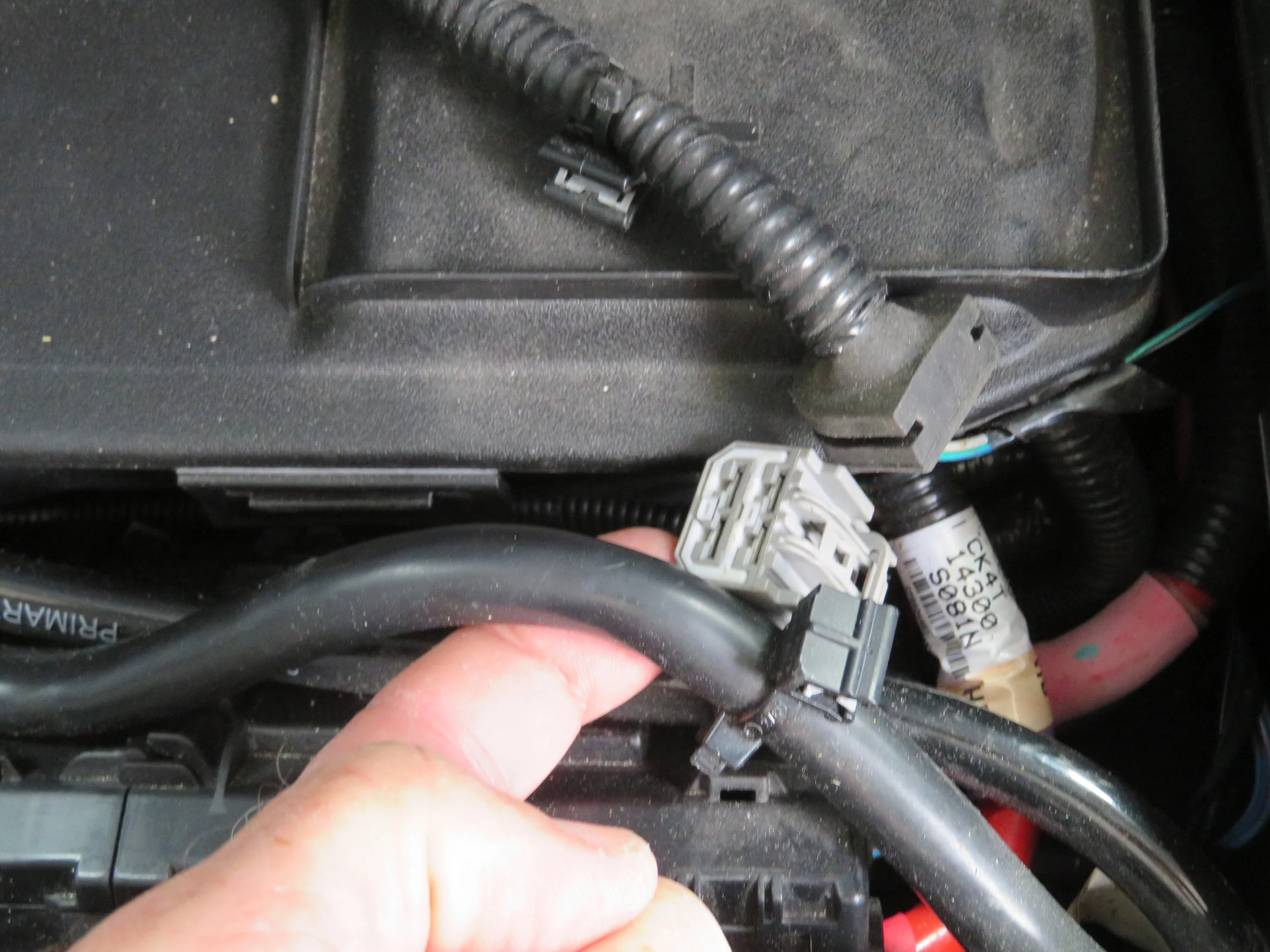
Connector located under driver's seat
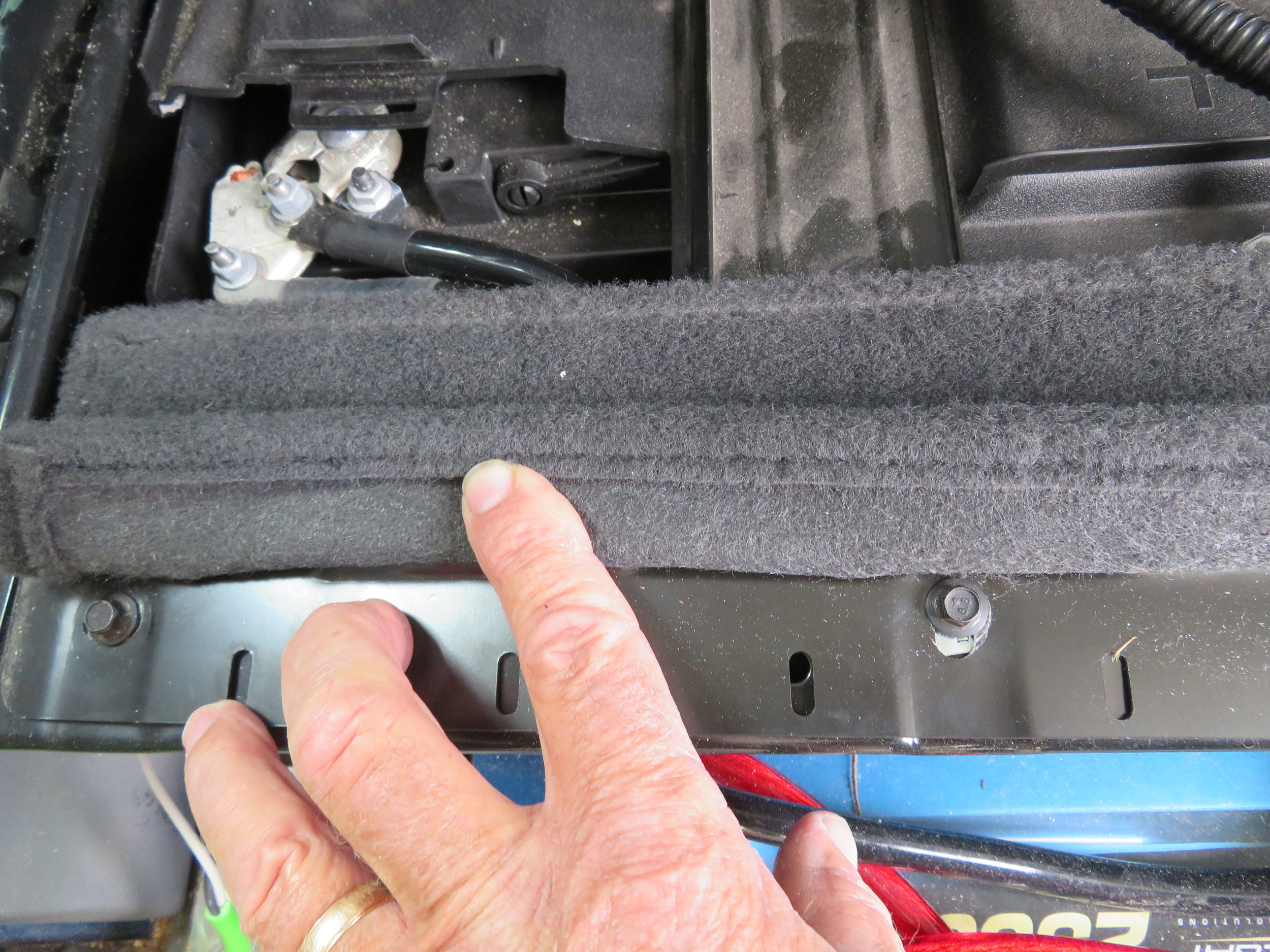
The first step was to locate the connector under the driver's seat. With our non-electric, manual seats, the process was fairly simple:
Move the driver's seat as far forward as possible
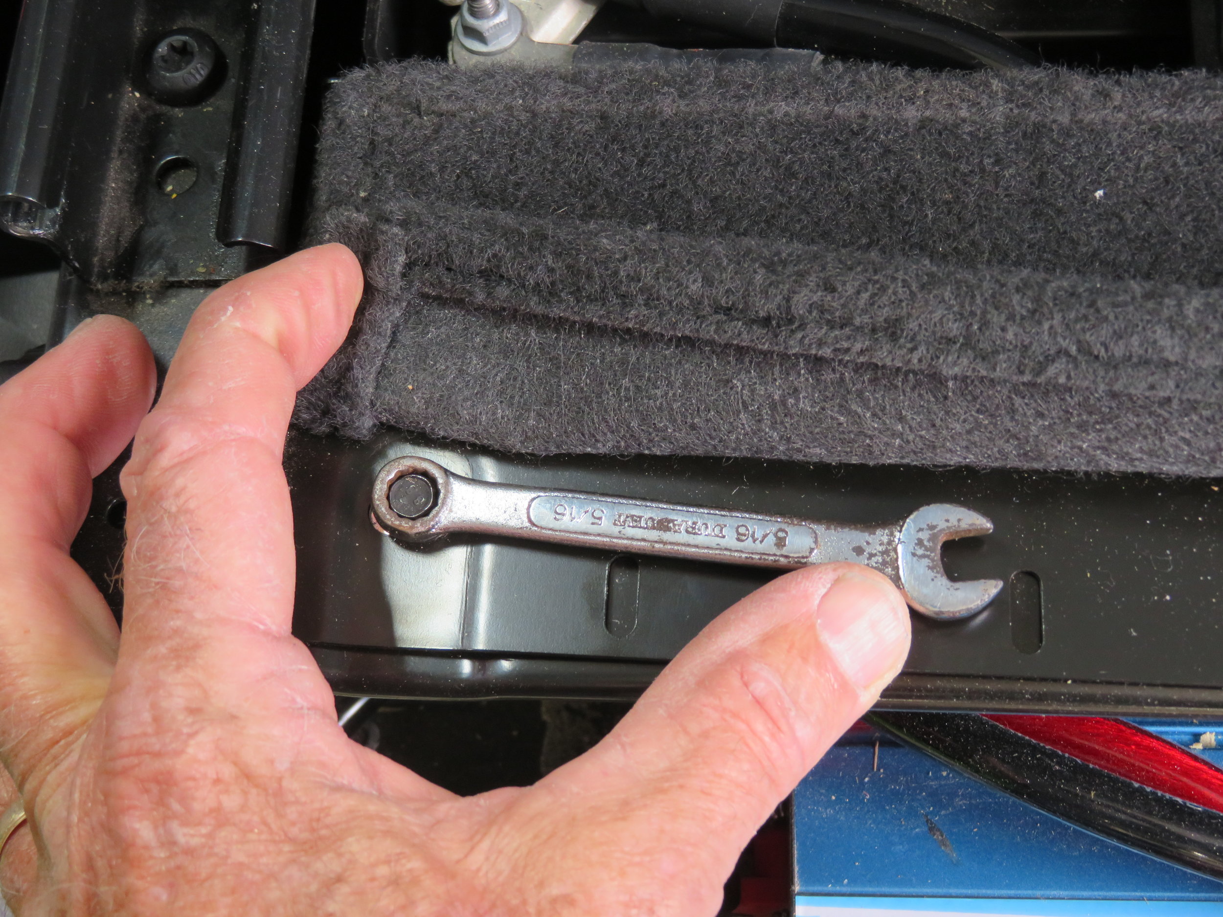
Lift the rear of the small piece of carpeting to access the two sheet metal screws and remove them.
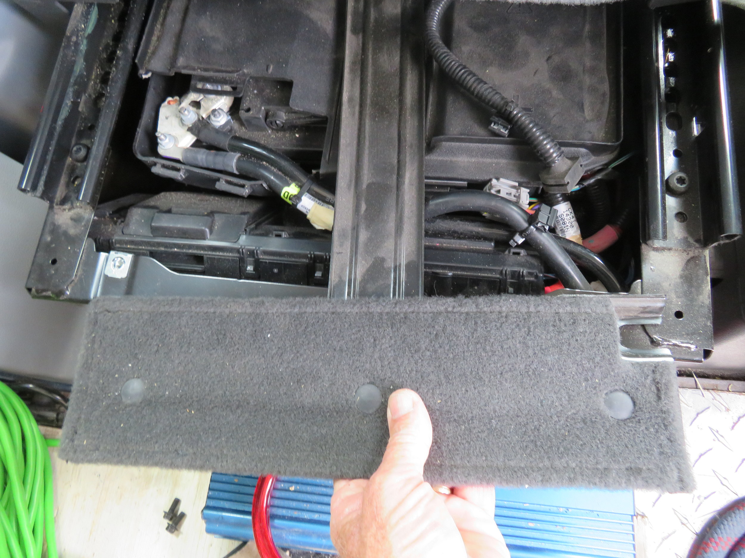
Disconnect the wiring harness from the T-shaped metal piece over the batteries and slide it back to remove.
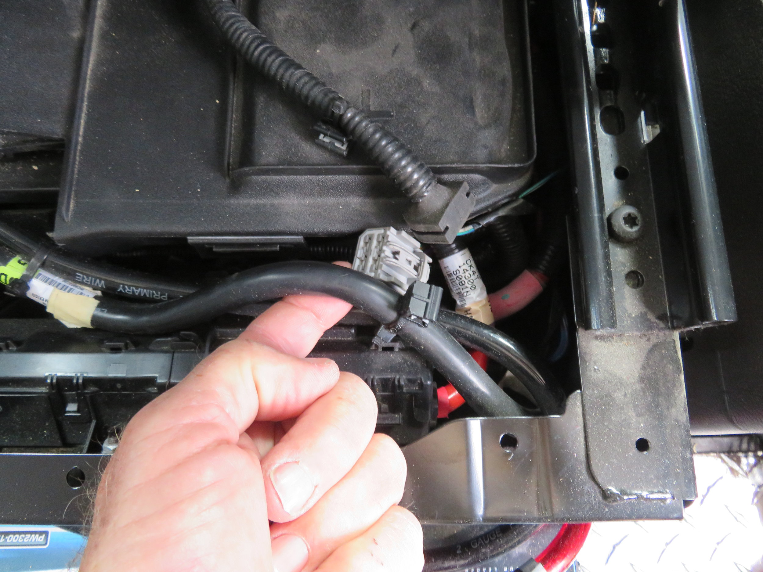
The connector on Blue was located under the wiring harness under the right side and behind the batteries. It took a few minutes to fish it out.
Snap the new mating connector onto the switch output connector and tuck it back down out of the way. The pigtails are long enough to route through one of the vent slots on the rear of the seat base.


As mentioned before, the switch outputs are fused at 20 amps. Therefore, any wiring connected to the switch outputs must be capable of handling 20 amps or include a smaller fuse. (I have an article that talks about adding a DC circuit to a boat, and the principles are the same.) To safely carry 20 amps, the wire size must be at least AWG10. I chose to use AWG8 wire just to add a little safety margin.
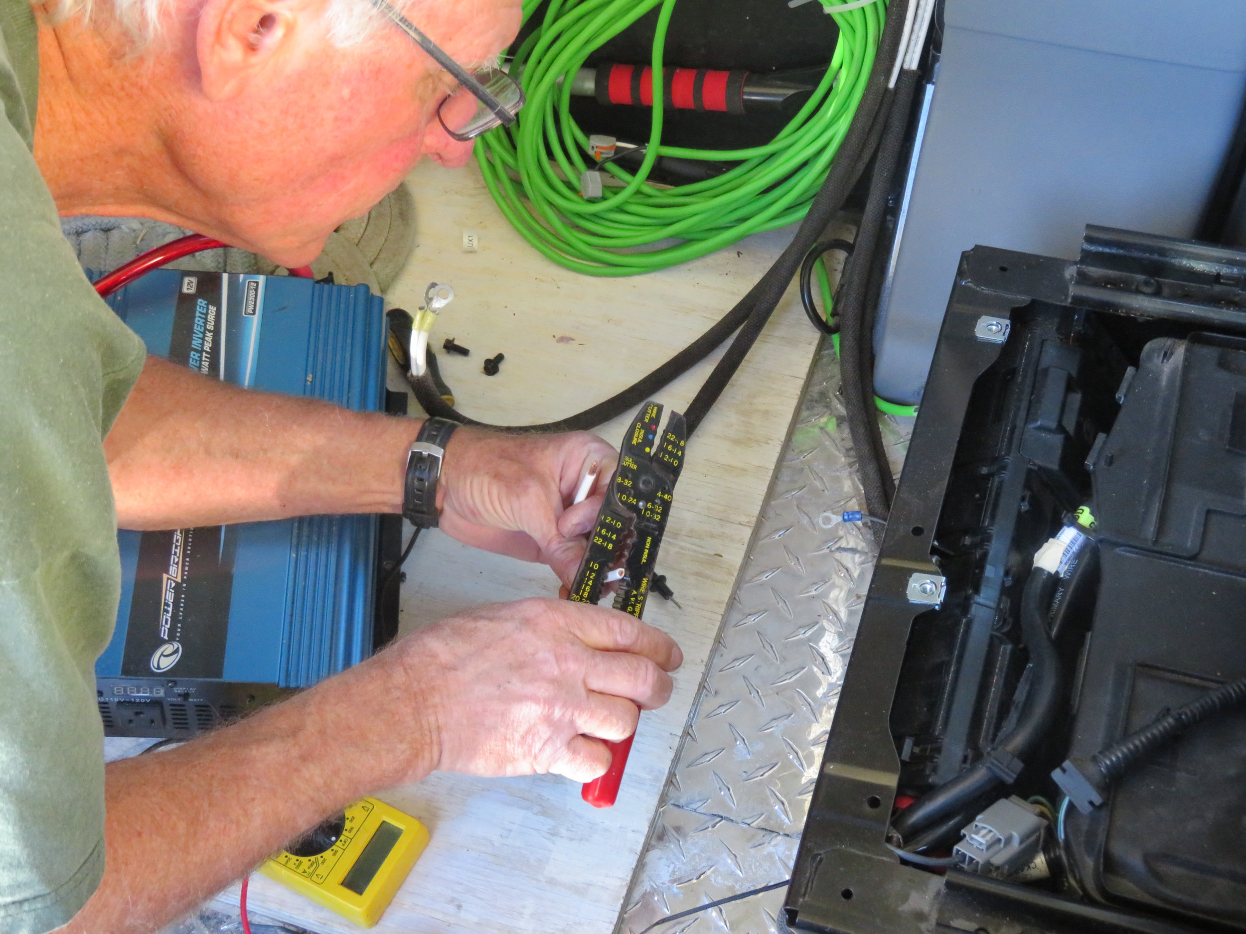
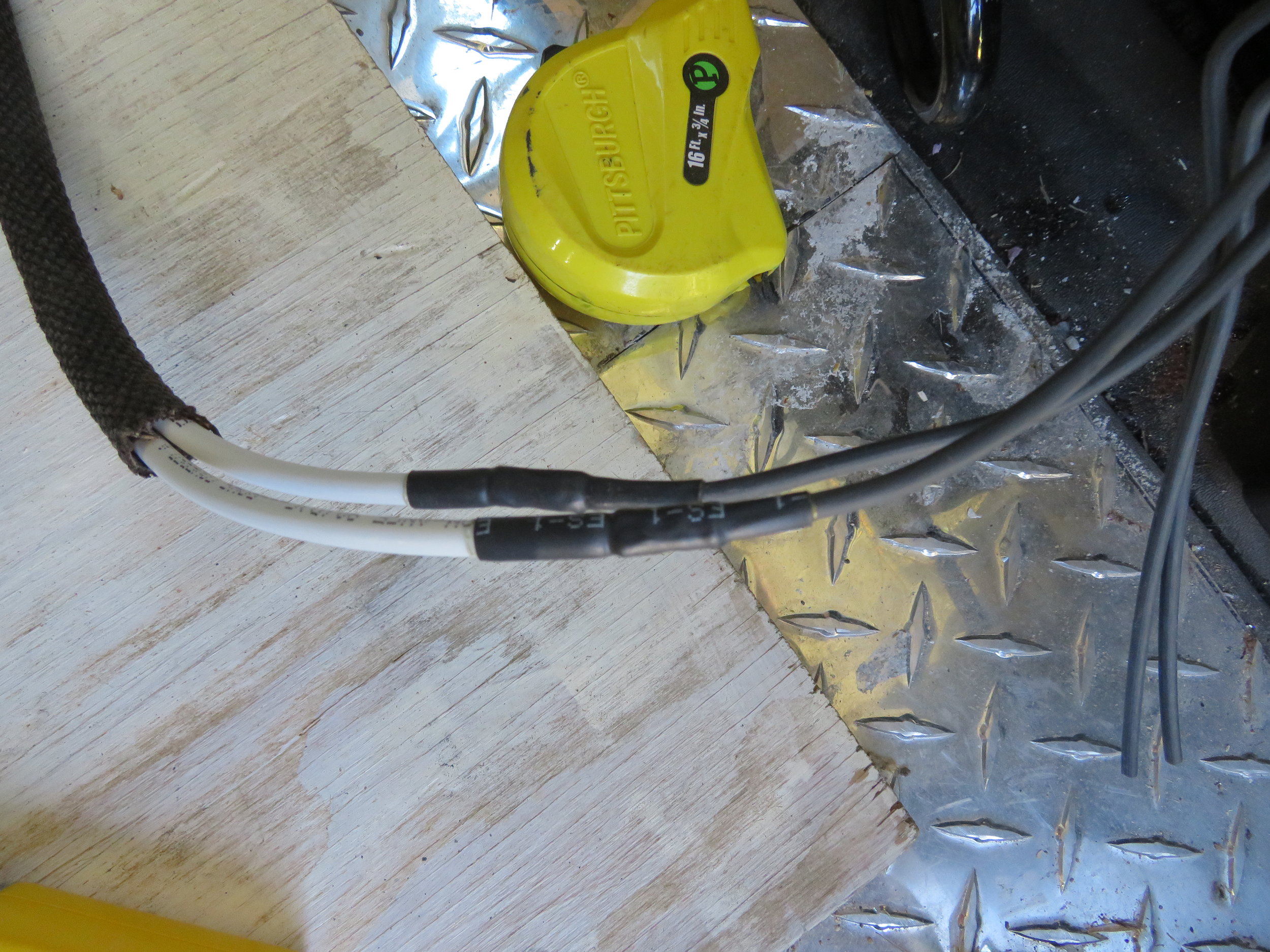


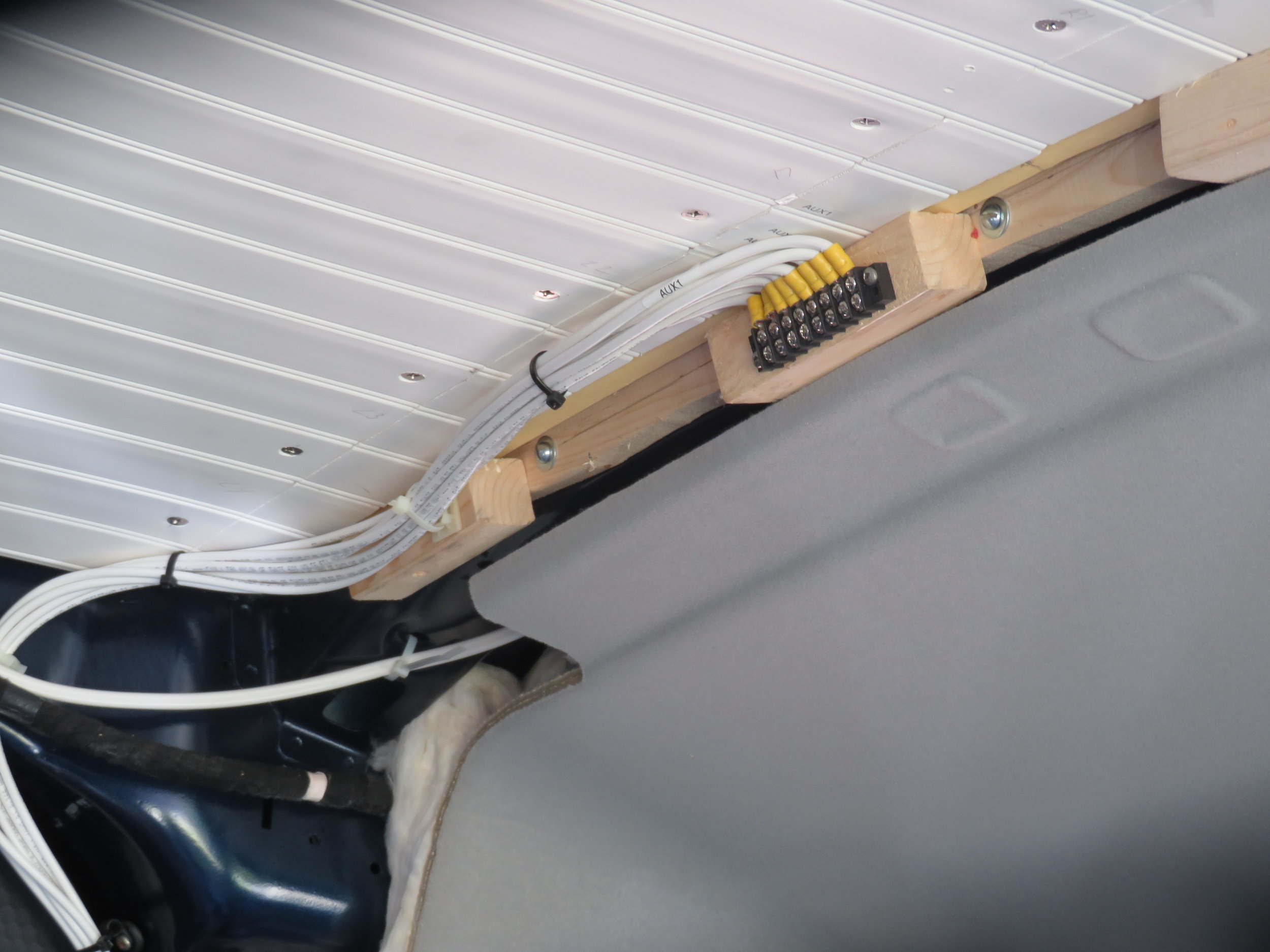
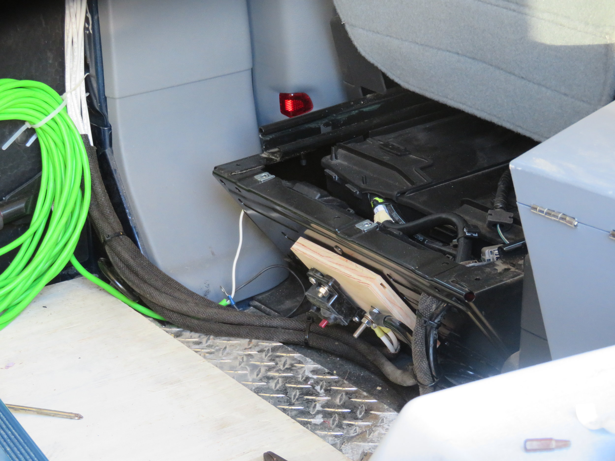
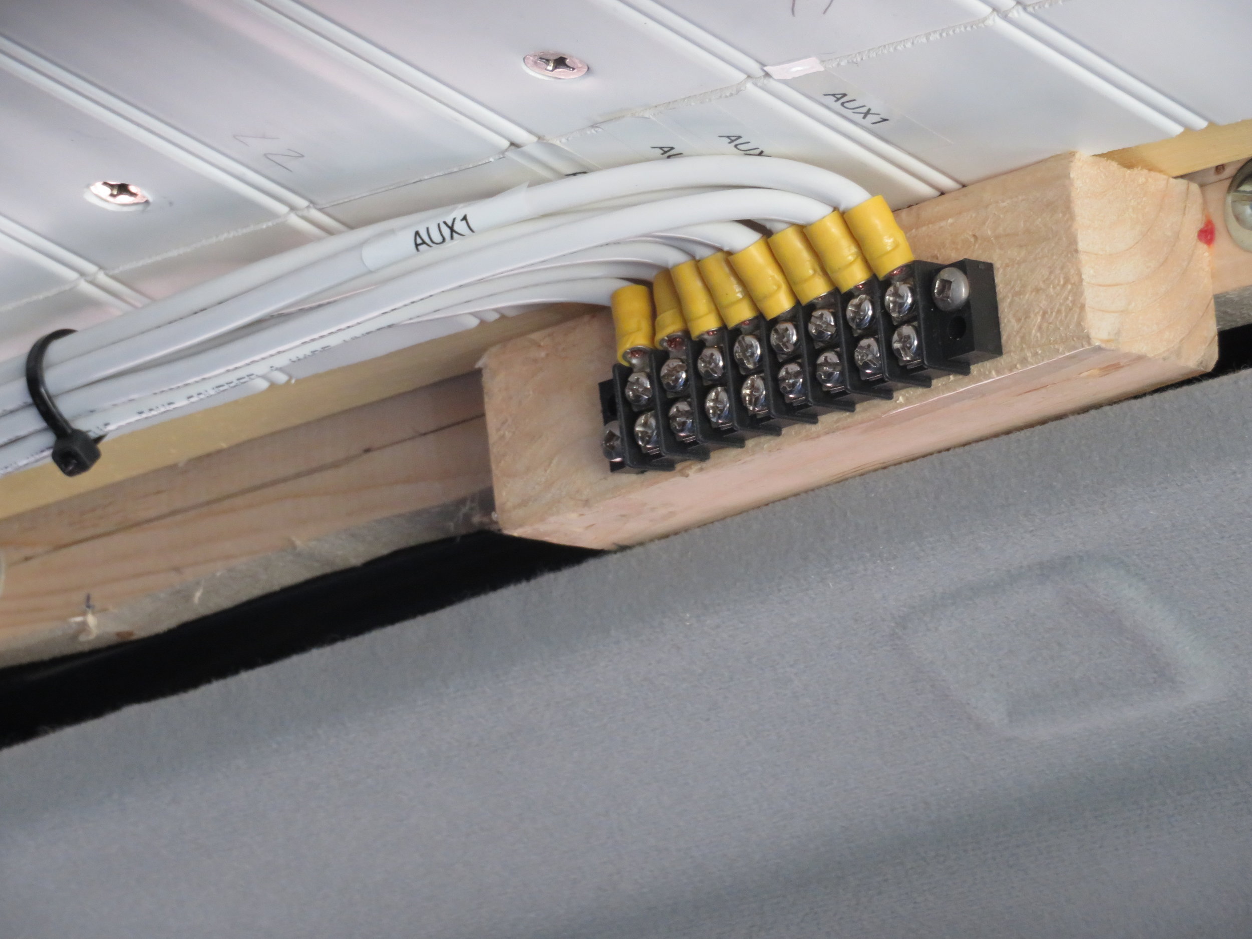
I connected a wire to each of the switch outputs by using the included crimp connectors and sealed them all with heat shrink. The wires were bundled together and routed to the terminal strip. I could have used the chassis for the return ground path, but I used four return wires instead. It's overkill, I know, but I'm hopeful I'll never have problems with it. I used cable sheathing to protect the wires from chafe between the connector and the point at which the wires will be routed behind the cabinetry. The negative return wires were routed to a terminal post I added to a chunk of wood which I mounted on the back of the driver's seat base. A heavy, 2/0 wire connects the terminal post to the negative post of the battery.
In the future, I plan to have an inverter connected to the starter batteries that can be powered by the alternator when the engine is running. It will also use this terminal post. The inverter will use a 120 amp breaker, which is shown in the picture mounted next to the terminal post. If I buy an inverter with a remote switch capability, I may use one of the auxiliary switches to switch it on and off. That way, there's no chance of forgetting that it's on and draining the starter batteries after the engine is shut down.
Once all the wiring was completed, I re-attached the wiring harness to the T-shaped bracket then screwed it back in place. The last step was to use a DVM to check that I had 12 vdc at each of the terminal pairs when the ignition was on and the appropriate switch was in the 'On' position.