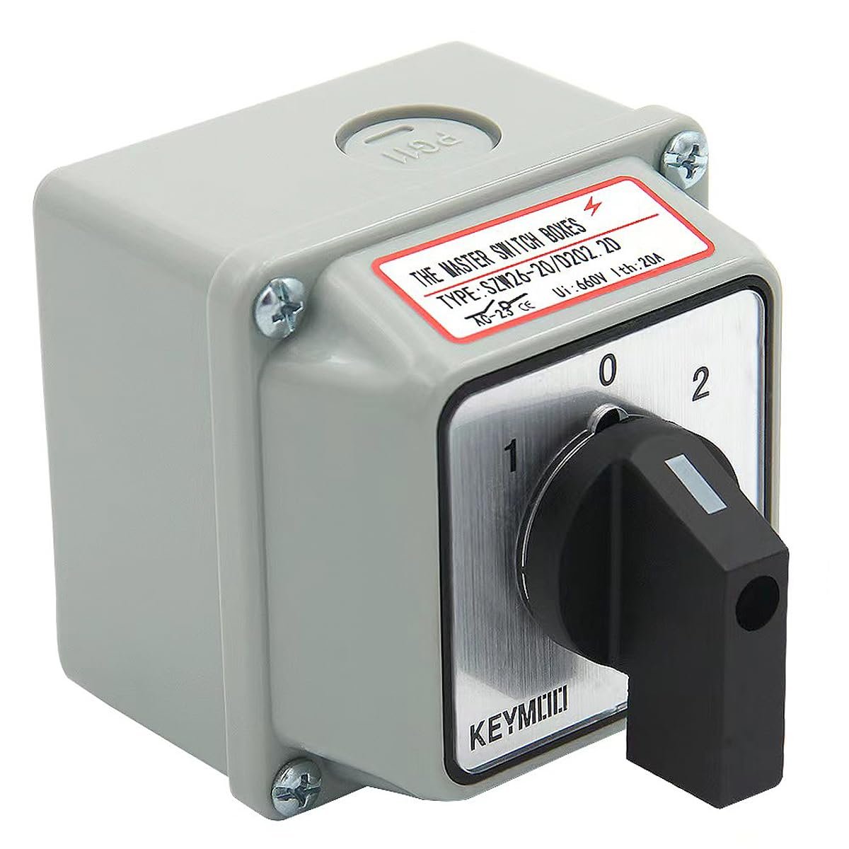
How to Wire a Rotary Changeover Switch
/One of the latest upgrades to Blanche, our Promaster camper van, was to add a shore power connection. In the past, when we’ve been in a campground with power, we’ve used an extension cord from an outlet strip inside the van to the campground power grid. It was a little cheesy - it was routed out the driver’s door.
A major improvement was made by adding a small compartment on the side of the van. The compartment has a door, which when opened, allows us to connect shore power directly to the van. I’ll talk more about installing all this in a later blog, but part of the upgrade was to add a rotary changeover switch that allows us to easily switch between shore power and power from our inverter. Wiring the rotary changeover switch is a little on the complicated side, however, and I thought I’d devote this blog to how it should be wired.
The switch is actually quite useful. It can be used to connect the van’s AC outlets to either of two power sources like, in our case, shore power or our inverter, or maybe a generator and shore power. It could also switch a power source to one of two loads - perhaps you’d like your solar panel to charge either of two batteries.
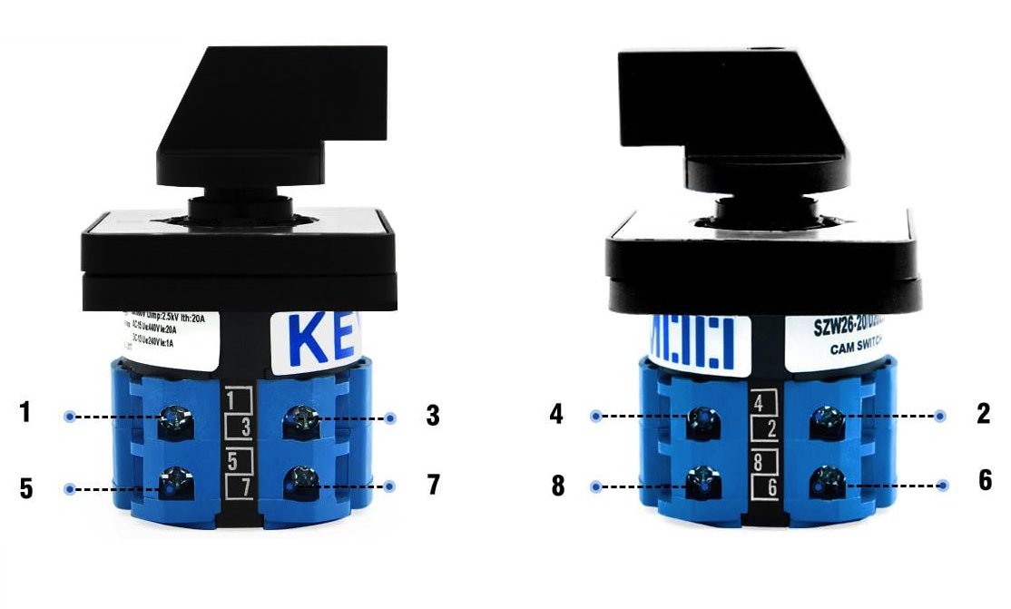
The switch has three switch positions and eight terminals. In position 0, no connections are made between the terminals. The following sketches show what connections are made in each of the other two switch positions:
In position 1, terminals 1 and 2 are connected, as are terminals 5 and 6.
In position 2, terminals 3 and 4 are connected, as are terminals 7 and 8
Probably the most common use of the switch is something similar to what we used it for, and I’ll use this as an example of how to wire the switch. Here’s what we want:
In Position 1, We want Shore power Connected to our outlets
In Position 2, We want the Inverter Connected to our outlets
The power cables we’re using have three conductors, each with a different color.
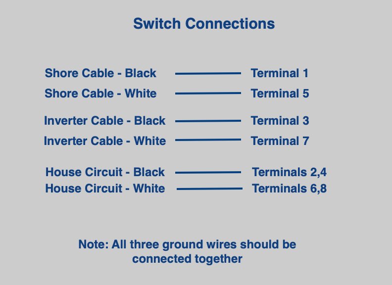
One way to wire the switch is to make the connections shown below:
So from above we can see that we should connect the black conductor of the shore power cable to terminal 1 of the switch, and so on. This will result in a circuit diagram like this:
So this is how the switch works:
In position 1, you can see that the shore power black conductor is connected to terminal 1, then thru the switch to terminal 2 and finally to the hot, or black conductor of the house circuit.
Also the shore cable white conductor follows a similar path to the house circuit neutral wire.
In position 2, the shore power conductors are disconnected. The black wire from the inverter is connected to terminal 3, thru the switch to terminal 4, then along the jumper to terminal 2 and on to the house hot wire. Likewise, the inverter white conductor connects to terminal 7, thru the switch to terminal 8, along the jumper to terminal 6 and on to the house circuit.
The three ground wires aren’t shown in the diagrams, but they should all be connected together.
Once all the connections are made and the switch is attached to the box, our shore connection looks like this:
If you haven’t fallen asleep by now and actually read this far, you may be interested in the YouTube video (here) we did that goes into more detail about making the connections.
See you next week…


