

The Blue View - Repairing the GPS
/We have a nice Raymarine chartplotter/GPS in the cockpit that we installed in 2004. The teak panel it is attached to has a cutout that was made to fit it. Unfortunately, it died about three years ago, and when we tried to order a replacement, we found that it was no longer being produced. This was somewhat of a dilemma since we couldn't find anything else that would fit the cutout. We did manage to find a used one on eBay, but it, too, died about a year later.

Eventually, we will buy another panel mount GPS and modify or replace the teak panel, but in the meantime, it isn't all that critical. We have several other GPSs aboard - a couple of handhelds, an antenna that feeds locational information to our Nav station chartplotter, and our tablets all have GPSs built in. We like having GPS information displayed in the cockpit, however, so I mounted one of the handhelds on the pedestal.
The problem with our handhelds is that they run on two AA batteries which need to be replaced every ten hours or so. On a long passage, that's a lot of batteries. We have Garmin handhelds which do provide the option of using a power cable, however, so I routed a cable to the cockpit. Everything was fine for about six months. Unfortunately, the power cable is not all that weather resistant, and the contacts soon corroded. No problem – I cut the connector off and soldered the wires directly to the GPS contacts, then gooped it all up with silicone. That lasted about a year and a half, but eventually, enough moisture made its way in to corrode these connections as well. It stopped working about a week ago on our first attempt to leave Cape Town.
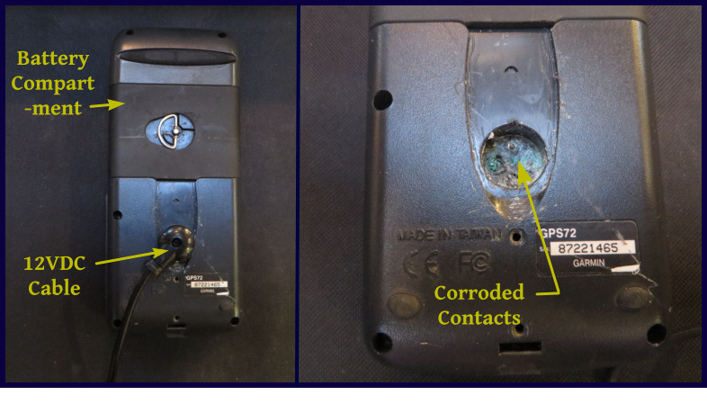
So our options were: do without, find a GPS locally that will fit into the teak cutout, or start over with another handheld GPS. There was one more option. I could make a 12 VDC to 3.2 VDC power converter and connect it to the battery contacts inside the battery compartment of the GPS. Since the battery compartment is nearly watertight, the connections inside should last a long time.
The voltage converter is a trivial circuit, and the parts can be found at any electronic hobby outlet like Radio Shack, Jaycar, or Jayco. Being the geek I am, I actually had the parts I needed aboard. I built, tested and installed the circuit on a rainy afternoon.
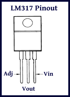
The circuit is based on an LM317 adjustable voltage regulator. By selecting the correct resistors, the device will convert the vessel's 10.5-14 VDC to any voltage between 1.2 VDC to about 8 VDC. All that is needed is the LM317, two resistors and two capacitors, plus a small generic circuit board to mount everything.

The output voltage is determined by the two resistors based on the following equation: Vout = 1.25 * (1+R2/R1) + Iadj * R2 Iadj is very small, and if we keep R2 small, the last term can be ignored. This simplifies the equation to: Vout = 1.25 + 1.25(R2/R1)
For an output of 3.2VDC, if we select a value of 240 ohms for R1, the equation becomes: = 1.25 + 1.25(R2/240) Solving for R2: R2 = (3.2-1.25)*240/1.25 = 374 ohms. Since 374 ohms is not a standard size, I used the closest standard size of 360 ohms for R2.
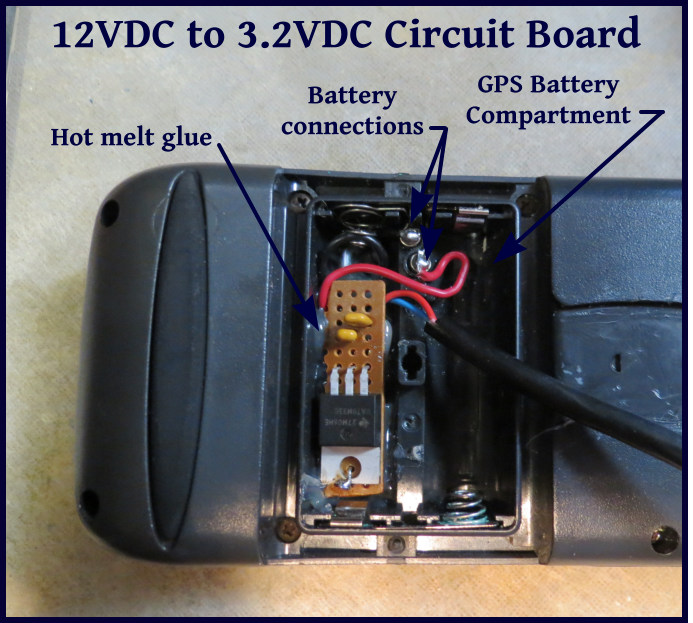
I mounted the circuit board inside the battery compartment – it was smaller than one AA battery – using hot melt from a glue gun to hold it in place. I drilled a hole in the battery compartment just large enough to slide the power cable through, then soldered it to the input pins of the LM317. The output of the regulator was connected to the plus and minus battery connections.
If your soldering technique is a bit rusty, we have three short videos on the subject. BTW, completing this project earns you a Geek 1st Class merit badge.
Editor's note from Marcie: I would rather suck water out of the bilge than re-read this blog post, but I know you geeks out there will appreciate it. ;-)