The Blue View - Windlass Chain Counter
/In the last two Blue Views, I talked about our experience with windlass controllers – what worked for us and what didn't and our own version of a handheld controller. In this Blue View, I want to show you how to make a digital chain counter.
The chain counter keeps track of the revolutions of the windlass gypsy, calculates exactly how much chain or rope is deployed, and displays the result in feet or meters on a small LED display. It uses very little power, drawing a few hundred milliamps when operating and only a few milliamps when it's not being used.
I know, I know – if you've never sailed, you probably couldn't care less. If you're an old salt, you're probably thinking “why don't you just mark the chain, ya idgit?”. Well, we do mark the chain, and use the marks as our backup system. We've actually used three different methods to accomplish the job - I talk about the different methods we've used in my book Nine of Cups Guide to Anchors and Anchoring.
I could argue that there are times when the marks are difficult to see, like when the chain is coated in mud or it's a dark and gloomy night - both of which are true. I could also argue that after we are hooked and I go forward to attach the snubber, it's nice to be able to double check, at a glance, that how much chain I think Marcie deployed is actually what's in the water. Probably the biggest reason I built my chain counter, if truth be told however, is that I'm a geek and just really enjoy these projects. Marcie is quite patient as I explain how much easier her job will be and that I'm doing this just for her – or that I can't imagine how we've managed to cruise all these years without whatever I'm planning to build.
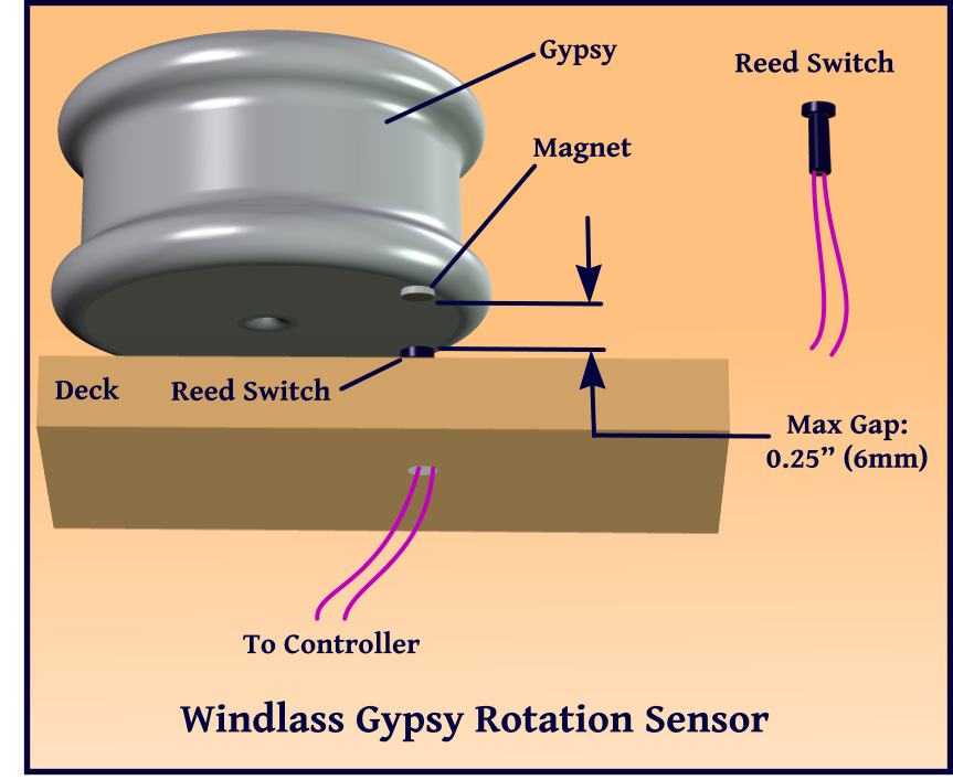
The first issue to resolve is how to keep track of the windlass revolutions. If a magnet is passed in close proximity to a magnetic reed switch, the magnetic pull causes the switch contacts to close. By attaching the magnet to the bottom of the windlass gypsy, and attaching the reed switch to the deck or the base of the windlass just below the gypsy, each rotation of the gypsy will pass the magnet over the reed switch, closing its contacts for a few milliseconds.
On our old Maxwell windlass, I had to drill a small indentation in the gypsy bottom in which to mount the magnet. I used Sika bedding compound to hold it in place and seal it from the elements. On our newer Lofrans windlass, a magnet sized dimple just the right size for a magnet was already part of the design. When we replaced the windlass last year, the gypsy came with a magnet already bonded in place.
The reed switch is mounted either in the deck or in the base of the windlass. The maximum gap between the magnet and the reed switch should be about 0.25” (6mm). The Lofrans windlass has a pre-drilled hole in the base that is intended for a reed switch, so all that is necessary is to drill a hole in the deck to pass the wiring through. As with any hole in the deck, the core should be sealed with epoxy to prevent damage. Once the switch and wiring are in place, the entire hole can be sealed with silicone.
The block diagram shows the general design. The handheld enclosure has two pushbutton switches which, when pushed, connect 12 vdc to the 'Up' or the 'Down' terminals of the windlass motor controller. The reed switch contacts are connected to one of the microcontroller input pins. The microcontroller knows that each time the reed switch contacts close, the gypsy has made one revolution, and from this, can calculate how many feet or meters of rode have been deployed. Since the microcontroller cannot tell which way the gypsy is rotating, it also checks whether the 'Up' button is being pushed. If the gypsy is rotating and the 'Up' button is depressed, the chain is being retrieved. If the gypsy is rotating and the 'Up' button is not depressed, the chain must be going out.
The display is a three digit, 8 segment LED display. Since the LEDs draw a measurable amount of current, the display is turned off when the windlass has not been operated for about five minutes.
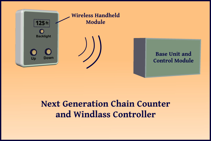
All in all, this was a pretty simple design, and we have been using it for about four years now. Generally, I am happy with it, but I plan to do a couple of things differently in the next version. First, the LED display in the current version is quite bright in low ambient light, but hard to read in bright sunlight. I will replace it with a backlit, daylight readable LCD display which should make it more visible in either the bright sun or at night. Also, with all the new technology now available, I plan to make the handheld module wireless and battery-powered, eliminating the cable. It should be pretty straightforward to incorporate matching 90mhz – 2.4 ghz radio transceivers in the handheld module and in the control module mounted in the forepeak locker.
For those of you who are interested in building your own windlass controller and chain counter, I am happy to provide the design details for the current version – just send us an email requesting them. Alternatively, if you aren't in a hurry, I plan to build the next version during the first few months of 2016, and should have all the design details available soon after. (I'd start working on it now, but I can't seem to find the right LCD display and RF Transceivers at the hardware store here in Bartica, Guyana – go figure.)


