
The Blue View - Prop Shaft Generator pt. 2
/ Design Considerations - Mechanical
Pulley sizes. The faster the generator spins, the more current it will generate. The ratio of the two pulley sizes determines how fast the generator will spin, which in turn determines how much current will be generated. To generate the maximum current, we want a very large pulley on the shaft and a very small pulley on the generator. On the other hand, when the engine is cranked on and we are motoring, the shaft will turn much faster than when we are sailing, potentially destroying the generator if it spins too fast. On Nine of Cups, taking max engine speed, transmission ratio, and the maximum generator speed into account, the largest pulley ratio I could use is 7:1 … i.e. ideally, the diameter of the shaft pulley should be just slightly less than seven times the diameter of the generator pulley. The closest I could come to this with the parts available locally was a 4.2:1 ratio.

Mounting
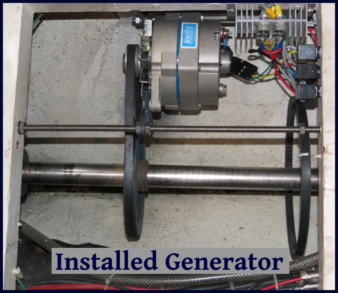
The bracket should allow the generator to be rotated towards the shaft so that the belt can be installed/removed, then tensioned. I made some sketches and worked with a local machinist to fabricate the bracket.
Design Considerations - Electrical
Converting to DC. The output of the generator is a three phase AC voltage which must be converted to DC in order to charge the batteries. This requires six rectifier diodes connected as shown in the sketch below. Most alternators have these diodes built into them, but in our brushless DC generator/alternator hybrid, the diodes are external. The diodes should be chosen to ensure they can handle the maximum output voltage and current of the generator. I used Vishay 95PF80 diodes.

Regulating the output. If the generator is spinning, it will be generating a current. If the batteries are charged, this current must be disconnected from the batteries to prevent them from being overcharged. One way to do this is to use a regulator that diverts the current into a dummy load when the batteries reach their charged state. Many companies that sell wind generators and solar panels also provide these charge controllers. We use the water heater as the dummy load.
Protecting the diodes and generator. When the engine is running and in gear, the generator RPMs will be much higher than when sailing. The open circuit voltage will reach several hundred volts, and the current when the load is diverted to the dummy load may overheat the generator. I added relays to the output of the generator to disconnect it when the engine is turned on. The complete circuit sketch, which includes the relays and charge regulator is shown below.

Measured output
I completed the project in Cape Town, and it was in use during our passage to Lüderitz. Something I plan to do during our Atlantic crossing is to quantify how many amps it produces at different speeds (our bottom needs a cleaning after being in Cape Town, making the speed transducer a bit sluggish, so we couldn't measure our speed through the water). The generator output varied from 2 to 8 amps, however, and not only did we not have to start the engine, we actually shut the wind generator down at times to save wear and tear on it, as we were producing more than we needed.
A side effect is that both the spinning prop shaft and the generator produce noise when we are sailing. After a few hours, though, the hum of the prop shaft and the whine of the generator soon become part of all the other background sounds - creaks, groans, squeaks, chirps - as Nine of Cups sails along, noticeable only when something changes. So far, that has been the only negative, and I regret not doing the project years ago.