

The Blue View - What Size Wire Do I Need - Pt. 2
/ Last week's blog discussed one aspect of determining the correct wire size for an electrical application – how much current a wire can safely carry. Another aspect that should be considered is the amount of voltage drop that will occur.
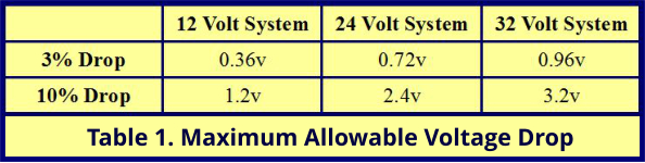
All electrical wire has resistance, and because of this resistance, as current flows through the wire, there will be a voltage drop. The amount of voltage drop that occurs depends on three factors: the length of the wire, the amount of current flowing, and the resistance of the wire. For some non-critical circuits, like cabin lighting, a 10% voltage drop is acceptable, but for most other circuits, a 3% voltage drop is the maximum allowable. Table 1 provides the maximum allowable voltage drop, in volts, for 12 volt, 24 volt and 32 volt systems.
The first step in determining the voltage drop is to measure the wire length. I use my tape measure and measure each section of the wire run. I always round up and add a couple feet, or half a meter, for good measure - it is better to overestimate. I measure the return wire path to DC ground as well.
The second variable, the amount of current the wire will be carrying, may or may not be simple to calculate. If the wire is used for a single device – a bilge pump for example – all that is needed is to check the label on the device or refer to the owner's manual. If there are several devices connected to the circuit, the process is more complicated and involves a worksheet and a few calculations. I will describe the process in next week's blog. For purposes of this week's blog, let's assume we have a single device being powered by our circuit.
We now have all the information necessary to determine the necessary wire size. Follow these steps:
- Calculate the maximum resistance per foot using the formula:
Ohms per foot = Allowable Voltage Drop / (Current in Amps x Length of wire in feet)
- Use Table 2 to find the wire size. Select a wire size that has a lower resistance per foot than the calculated resistance.
For example, let's say we have a 12 volt system and are adding a circuit for a new chart plotter that draws 3 amps. The round trip length of wire is 35 feet. We want no more than a 3% voltage drop in the circuit. For the equation above,
Allowable voltage drop = 0.36 volts (from Table 1)
Current in amps = 3
Wire length = 35 feet,
so the maximum resistance per foot would be 0.36v/(3amps * 35') = .0034 Ohms/foot.
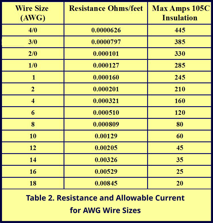
Looking at Table 2, wire size AWG 14 is the smallest wire that has a resistance less than .0034 Ohms/foot. So, AWG 14 wire is the smallest wire we can use and still have a voltage drop of less than 3% for our circuit.
The last column in Table 2 lists the maximum allowable current that the various conductor sizes can handle under ideal conditions. (This should look familiar if you read last week's blog.) This value is for quality marine wire with insulation rated for 105ºC. If more than the allowable current is passed through the wire, the wire will heat up enough to melt the insulation, creating a fire hazard. If you use wire with a lower temperature rating for the insulation, the wire cannot handle the same amount of current before the insulation begins to melt. Likewise, if the wire is run through an engine compartment with a higher ambient temperature, or if several current carrying wires are bundled together, the insulation may melt with a current less than the listed maximum current.
Table 3 lists some multipliers that can be used to estimate the reduction of the maximum allowable current for different situations. These are somewhat conservative values. If more than one situation applies, the multipliers should be combined.
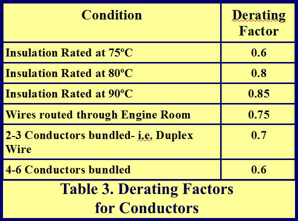
For the chart plotter example, if a two-conductor duplex cable with AWG 14 wires is run from the distribution panel, through the engine compartment, and on to the new chart plotter, the maximum allowable current would be less than the 35 amps shown for AWG 14 wire in Table 2. Since the wire has two conductors, we have to derate the current capability by 0.7, and because the cable passes through the engine room, it must be derated a further 0.75. So, the AWG 14 wire will only be able to handle 35* 0.75 * 0.7 = 18 amps. The chart plotter only draws 3 amps, however, so the AWG 14 duplex wire is more than adequate.
The important thing to remember is that the wire must be adequately sized to meet both criteria; it should have an acceptable voltage drop and be large enough so as not to overheat. Most often, if a given wire size meets the first criteria, it will also meet the second, but not always, so it is important to check both.
Next week, I plan to talk about the process of calculating the total load on a circuit when there are several devices connected. Stay tuned.