
The Blue View - Troubleshooting Engine Tachometers
/We interrupt our inland travel once again to bring you another Blue View. Believe it or not, some folks prefer boat talk to travel talk. Travel resumes tomorrow.
In the last Blue View, I talked about troubleshooting problems with engine gauges, specifically temperature, oil pressure, and water temperature gauges. In this BV, I'll discuss diagnosing problems with tachometers.
Despite the fact there are different tachometers intended for outboard two stroke and four stroke engines, inboard gasoline and inboard Diesel engines, they all basically work the same - they all convert the number of pulses per second on the input terminal to engine RPMs.
Different types of engines generate these pulses by various methods. Some engines generate the pulses electronically, and there is one pulse per engine revolution. Many inboard Diesel engines use the alternator output as the tach input, and the number of pulses per revolution is a function of the number of alternator poles and the ratio of the alternator pulley size to the engine pulley size. Other engines use a magnetic pickup mounted next to the flywheel and generate one pulse for each gear tooth - in which case, there are two or three hundred pulses for each engine revolution.
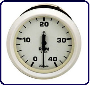
Size, shape and color aside, tachometer manufacturers usually have different models available for different engine types. One option is the full scale range. The old Ford Lehman engine on Nine of Cups has a maximum RPM of 2800, and I don't want a tachometer that indicates a red line at 6000 RPMs and a full scale of 7000 - my idle speed of 800 RPMs would barely deflect the needle. Another option is the "pre-calibration" of the tach. Most manufacturers have models calibrated for the more common engines, thus avoiding the necessity, in most cases, of requiring specialized equipment and an hour or two of time to calibrate each tachometer when it is installed.
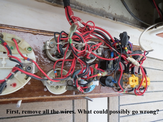
Okay, enough theory - let's get on to troubleshooting. There are typically four problems that can occur with the tach: it is totally inoperative and always displays zero; the needle is stuck or permanently pegged; the needle is erratic; or the RPMs are consistently off - either low or high. To test the tachometer, you will need a digital multimeter.
Inoperative
Check the obvious - when the ignition is switched on, is there 12vdc (or 24vdc) between the positive terminal and negative terminals when measured with a voltmeter? If not, use your voltmeter to determine whether the problem is in the wiring on the positive side or the ground side.
If the voltage is correct, the next step is to check the input signal. Remove the signal wire. Set your voltmeter to AC volts and connect it between the signal wire and ground. Start the engine and set the speed to idle. You should get a reading on the multimeter that varies with engine speed. If the tachometer is connected to the alternator, this reading should be a minimum of about 5VAC, otherwise it will be more like 0.3VAC. If you get any indication of a pulse stream, reconnect the signal wire, and if the problem is still evident, the culprit is most likely the tachometer itself.
If you get no indication of a pulse stream, disconnect the tachometer signal wire on the engine and repeat the test there. If you detect a pulse stream at that end, the problem must be in the wiring. Otherwise, the problem is in the signal generator.
Needle is Stuck or Pegged
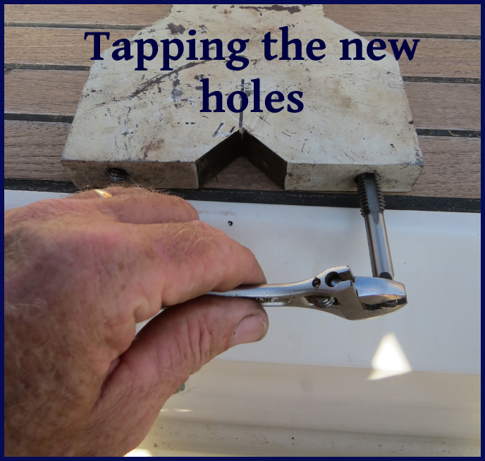
The needle could be stuck in one place or permanently pegged for a couple of reasons. One is that the tach case is tightened down too much and has distorted due to heat or vibration. Try loosening the clamps holding it in place, then tapping the front face piece gently. If the needle frees itself, retighten the tach clamps just enough to hold it in place.
Another possible cause of a stuck needle is over stressing it electrically. This could happen, for example, if the battery cable was disconnected while the engine was running, the tachometer was subjected to large rf noise from a badly tuned or poorly grounded HF radio or from a lightning strike. It is sometimes possible to correct the problem by placing a magnet on the faceplate over the needle and "pulling" the needle free.
Erratic Reading
An erratic reading is usually due to a poor connection somewhere. Start the engine and wiggle each wire leading into the tachometer to try to isolate the culprit. Have someone watch the tachometer while you wiggle the wires on the engine side.
Another possible cause of an erratic reading is electrical noise. Does the problem only occur when the autopilot is running or when sending emails via your HF radio? The problem can sometimes be corrected by putting a resistor in the signal line. It should be placed on the tachometer end of the wire. You may have to experiment with resistor sizes. A 10k ohm, 1/4 watt resistor will often correct the problem without affecting the calibration. If not, try a 1k ohm, 1/4 watt or a 100 ohm, 1/4 watt resistor.
Readings are Consistently Low or High
This is a symptom of the tachometer being out of calibration, which usually doesn't occur unless something is changed. Did you recently replace the tachometer? Alternator? Pulley on the alternator or engine? Some tachometers have multi-position switches or jumpers located on the back or which are accessible through openings on the back. Check that the jumpers are not loose, or if there is a switch, it is possible that the contacts are dirty. Try rotating the switch a few times, then moving it back to its original position.
If necessary, it is usually possible to recalibrate a tachometer. Many older tachometers use switches to set the gross range, and a potentiometer to either fine tune the range or adjust the gain. If the tach is only off by 10%-20% or less, you may be able to recalibrate it using only the potentiometer - otherwise, you will need the manufacturer's documentation to correctly set the switches. Newer tachometers often use a software program for calibration, and you will need a computer, the software and any necessary cabling to calibrate the tachometer.
You will also need a strobe tachometer to determine the engine speed. This is an adjustable strobe light with a digital readout. They used to cost hundreds of dollars, but can now be found online for less than $50. I have also seen apps for smartphones and tablets that simulate a strobe tachometer, and while I can't vouch for the accuracy of these apps, they are probably good enough to calibrate your tachometer to within 5% or so. You can rent, borrow or buy a good one, buy a cheap one or try one of the apps. Then you need to put a mark on the big pulley on the front of the engine. This can be a small piece of tape, a line drawn with a marker, or a dot of paint, just as long as it can be easily seen when you shine a light on it.
Start the engine and increase the engine speed until the engine tachometer displays about half of the engines maximum RPMs. Set the strobe tachometer to the same RPM setting and aim the strobe at the pulley. If the engine tachometer is exactly in calibration, the mark on the pulley will appear to be frozen in place. More likely, the mark will appear to move. If it is slowly drifting around the circumference of the pulley, your tachometer is only slightly out of calibration. If the mark appears randomly all around the circumference of the pulley, your tachometer is very much out of calibration.
Adjust the frequency of the strobe tachometer until the mark on the pulley appears to slow down and eventually stop. The digital display of the strobe tachometer will now be showing the correct engine speed. Adjust the potentiometer on the back of the engine tachometer (or adjust the tachometer using the software) until it reads the same as the strobe tachometer. Check the calibration at 1/4 throttle and 3/4 throttle. In a perfect world, the engine tachometer will now match the strobe tachometer at all three engine speeds. More likely, you will need to adjust the calibration until the error is minimized throughout the engine range.
Now that your engine tachometer problem is figured out, the crew of Nine of Cups is picking up where we left off in the wilds of Swaziland and South Africa. Stay tuned...