Cape Town just never wants to let us go. Every time we've tried to leave, some malfunction occurs. When we were last here in 2007-8, we had done all our pre-departure checks, had cast off the lines and were backing out of our slip when the gearshift lever came loose. We were stuck in reverse, heading down a narrow, dead end channel with expensive boats on either side, and the old adage, “aim for something cheap”, came to mind. At the very end was an old concrete work-boat wharf. I headed for it, and killed the engine. Between the two of us, were able to fend off and tie up long enough to make the repair with only minor damage to the teak brightwork.

This time, we didn't get far before the headsail tore, the alternator went on the fritz and the backup cockpit GPS stopped working. Now that we have a few weeks grace on our visas, we handed the headsail over to a local sailmaker and bit the bullet to have a new one made, but the alternator and GPS are mine to troubleshoot.

Cups has a simple charging system. Our house batteries are all in parallel, and connected directly to the alternator output. The starter battery is isolated from the house batteries with a diode and a thermal breaker (See the Blue View on charging two battery banks). The alternator is a high output P-type with an external Balmar voltage regulator. The regulator senses the battery voltage and controls the alternator output by varying the alternator field current.
Our alternator was working when we started the engine and left the marina, but sometime in the next half hour, the output current went to zero and it stopped charging the batteries. There was no alarm. The original symptom was that the engine voltmeter was reading 12.25 VDC. If the alternator was working, the voltage would have been well over 13 VDC. I went below and checked my battery monitor and confirmed that the alternator output was zero.
This is the process I used for troubleshooting the alternator :
Visual Checks
Marine alternators and electronics are pretty robust, and while they do fail on occasion, there is a much higher probability that the problem is something simple like a loose or corroded connection or a loose belt. I inspect the obvious things first – is the drive belt loose; are the alternator connections tight; are the regulator connectors tight; is there any sign of corrosion on any of the connectors, connections or wires; any loose or broken wires? Often the problem is obvious, and if you spot something flaky, but not causing a problem at the moment, fix it now before it does become a problem.
Initial Checks
For the initial checks, I use a digital multimeter. I shut down the wind generator and disconnect the solar panels (actually it is easier for me to drape a tarp over them), then measure the voltage across the positive and negative terminals of the house batteries. It is typically around 12.6 VDC, but could be anywhere form 12.25 to 12.80 VDC. Then I measure the voltage between the positive and ground terminals of the alternator. Since I don't have an isolation diode between the batteries and the alternator, I expect the voltage to be close to the the same as the battery voltage. (If I did have an isolation diode, I would expect the voltage across the alternator to read 0 VDC). If the alternator voltage is not the same as the battery voltage (or 0 VDC if an isolation diode is in place) then the problem lies between the alternator and the battery.
Things to check are:
Cable and connections between the battery and alternator.
Ground connection from the alternator.
Blown fuse - although there is rarely a fuse in the connection between the alternator and battery
Open current sense resistor (these are used by battery monitor systems to measure alternator output, and have been known to overheat and open).
If there is an isolation diode in the circuit, it may have shorted.
If the first check was okay, I start the engine, let it idle for a minute or two, then increase RPMs to 1/3 full throttle. The voltage across both the alternator and battery should increase by at least a volt. If not, the problem still exists.
If the alternator voltage did not increase, the problem lies with the alternator or regulator
If the alternator voltage increased, but not the battery voltage, then the problem still lies between the two.
Things to suspect:
Open isolation diode
High resistance in the cable or connections between the alternator and battery.
Alternator Checks
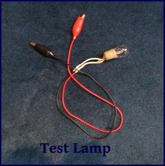
If I've gotten this far, there is a problem with either the alternator or the regulator, and the next step is to determine which one. To do this, I first simulate the voltage regulator using a test lamp. The lamp must draw at least 1 amp – I use an old 24w 12 VDC anchor light from the pre-LED days, and to which I have soldered two 18” wires. I test the bulb by connecting it across the battery. I disconnect the field wire from the alternator (on my alternator, the field terminal is marked “FLD”, but it may also be marked with “F” or “FIELD”), and I connect one lead of the bulb to it. I start the engine, then connect the other side of the bulb to 12 VDC. If the bulb lights up, the alternator is a P-type, and the alternator output voltage should increase. If the bulb doesn't light, the alternator is either an N-type or there is an open field circuit. Remove the lead from the 12 VDC and connect it to ground. The bulb may or may not light up, but the alternator output voltage should increase when the bulb is connected from the field to ground. In either case, I watch to see whether the alternator output increases and decreases as I connect and disconnect the bulb.
If the alternator output doesn't change when I connect and disconnect the bulb (and I am sure the bulb works), the problem must lie with the alternator. Depending on the situation, I may dig out the spare alternator and swap the bad one out; try to diagnose and fix the problem; or take it down to the local alternator repair shop. I've done each of these at one time or another.
Regulator Checks
On my Balmar voltage regulator, there are a host of connections – battery voltage sensors, battery temperature sensors, alternator temp sensors, tachometer connections, etc. Most are optional, or, as is the case with the battery temp and voltage sensors, will generate an error message if there is a problem. The first thing I do if I suspect a problem with the regulator is start the engine and see whether an error message is displayed. If there is, I use the Balmar manual to diagnose the problem. If there is no error message, there are four connections, power, ground, ignition, and field, that can cause the symptoms I have, and will not generate an error message.
The following is the procedure I use to determine the cause:
With the ignition off, I measure the voltage between the power connection and ground connection. It should be close to the battery voltage. If it is not correct, find the problem – it might be a blown fuse or a bad connection - otherwise continue.
I start the engine and measure the voltage between the ignition connection and ground. It should be between 11.5 VDC and the battery voltage. On Nine of Cups, the ignition connection is routed from the battery, through the ignition switch, then through the oil pressure switch, and finally to the regulator. If not correct, find the problem – otherwise continue.
With the engine running, I measure the voltage between the field wire and ground. It should be between 3 and 10 VDC. If not, and there is no error message, the controller is faulty – otherwise, the regulator is working.
So what did I find? The problem turned out to be the connection on the oil pressure switch for the wire that connected it to the regulator. The pressure switch was fine, as was the connection to the cockpit engine alarm. It took an hour or so to find the problem and another hour to replace the connector with a shiny new ring terminal – then, of course, most of the rest of the day to write the blog about it.