The Blue View - Alternative Energy Monitor

new alternative energy monitor When we bought our solar panels and wind generators about 15 years ago, we also bought a control panel and monitor to go with it. Although it was quite expensive, it seemed like a good idea at the time. It isolated and combined the inputs from up to three sources, provided a brake and “bump start” for the wind generators, and included a couple of meters to measure the voltages and amps being generated.

old alternative energy monitor

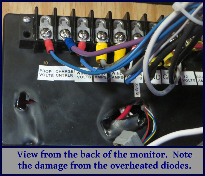
The marketing hype made it sound like it was something we wouldn't want to do without, but it didn't take long to realize we had wasted our money. The brake was ineffective in strong winds, the “bump-start” was never used, and the isolation diodes had a habit of overheating and frying (they actually melted the case on a couple of occasions). The volt and amp meters were only useful in determining whether the various inputs were still working, but when the voltmeter died a few years ago, the monitor lost even this functionality.

back of the old alt energy monitor

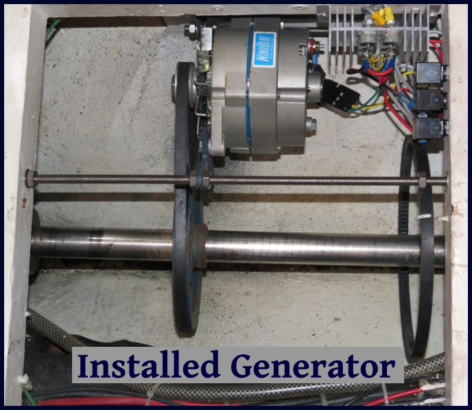
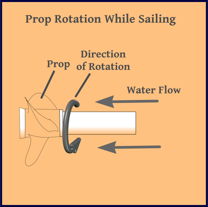
We now have three sources of alternative energy – solar panels, a wind generator/turbine and a generator that is attached to the prop shaft which produces power as we sail. It would be nice to have a simple monitor that would combine these three sources, and display the voltage and number of amps being generated by each source. In addition, it would be nice to keep a running total of the number of amp-hours produced by each input over the previous 24 hours.

I spent most of my working life designing microprocessor-based instrumentation, a career I enjoyed immensely, and it still remains my favorite hobby. We have our own home-brewed refrigerator/freezer controller, a windlass controller and chain counter, pump monitors, and a host of other gizmos ... some of which actually work. When I cut my teeth on microprocessor design several decades ago, it helped to have an advanced degree in electrical engineering and computer science, and required thousands of dollars in developmental tools to develop a microprocessor-based instrument. Now, the development software is often free, and I suspect the basics are taught in elementary schools. On my long list of things I planned to make when I got the chance, a replacement monitor was near the top. When I installed the new prop shaft generator, I decided to build a new alternative energy monitor.

When I was younger, processors were slower and memory was expensive, so it made sense to write software in assembly or C language, so the code would be fast and efficient. The newer processors are loaded with all kinds of hardware features, are orders of magnitude faster and memory is cheap. I have long been fond of Microchip Pic processors, and I especially like the Picaxe versions provided by Revolution Education. They are pre-programmed with download software and a Basic interpreter, making them very easy to use. All the development software is free. What might have taken me weeks or even months two decades ago, can now be done – even by an old guy like me – in days. I used a Picaxe 18m2+ processor as the core of the design.

monitor block diagram

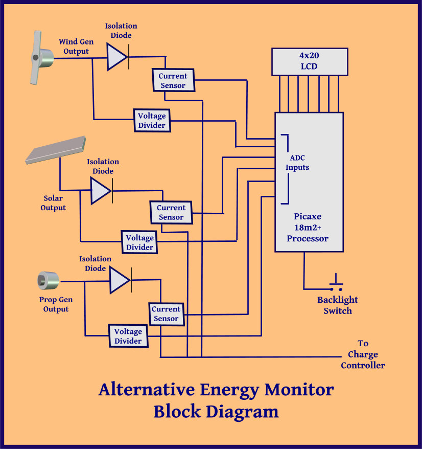
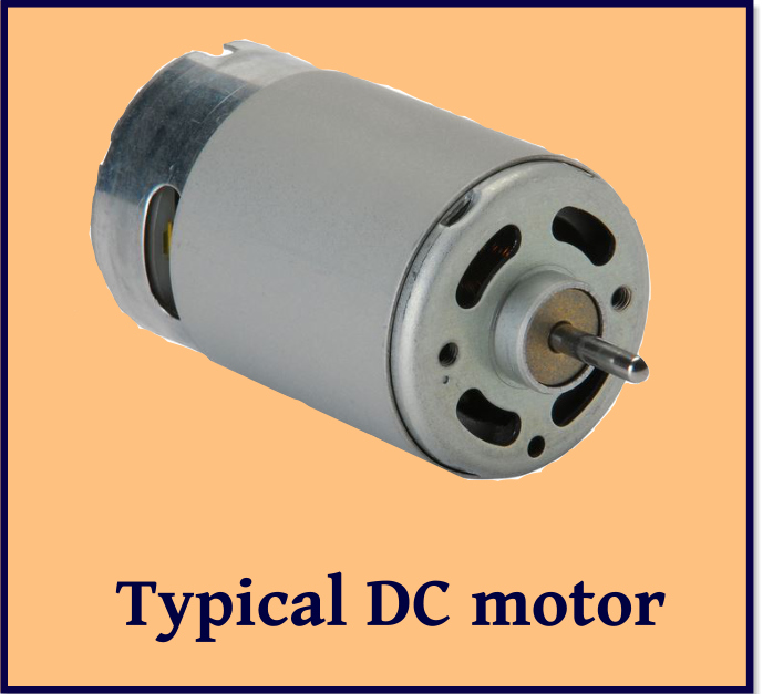
The block diagram shows the other components. The three inputs are isolated by diodes. (Without the diodes, current can flow in both directions ... when the sun goes down, the solar panels will draw current; when the wind isn't blowing, the wind generator will become a battery-powered motor.) The voltage generated by each input is scaled down using a voltage divider and measured with an A to D converter (ADC). The current is measured with Hall effect transducers – these devices provide a voltage output proportional to the current passed through them. The display is a 4 line, 20 character, backlit LCD. Since the backlight draws a measurable amount of current, it is only turned on when the button is pressed.

As instrumentation goes, this was a pretty simple design, and I am quite happy with the end result. I tackled it in four phases – the electrical design, the software design, the mechanical fabrication and the aesthetics. For those of you who are interested in building your own monitor, I am happy to provide the design details of the project – just send us an email requesting them.

Note from the editor: This is a pretty slick device, but please note that the Captain already had all of these components (backlit display, Hall effect transducers, diodes, Picaxe processors, etc.) aboard. In fact, there's an entire drawer (plus more) dedicated to electronic components alone. So, when I bring a few extra pieces of cloth or a couple shells aboard?  Just sayin' …

Note from the Captain: Well yeah – but the electronic components are essential ship stuff and very important. Sea shells???

The Blue View - Prop Shaft Generator pt. 2

shaft generator installed Design Considerations - Mechanical

Pulley sizes. The faster the generator spins, the more current it will generate. The ratio of the two pulley sizes determines how fast the generator will spin, which in turn determines how much current will be generated. To generate the maximum current, we want a very large pulley on the shaft and a very small pulley on the generator. On the other hand, when the engine is cranked on and we are motoring, the shaft will turn much faster than when we are sailing, potentially destroying the generator if it spins too fast. On Nine of Cups, taking max engine speed, transmission ratio, and the maximum generator speed into account, the largest pulley ratio I could use is 7:1 … i.e. ideally, the diameter of the shaft pulley should be just slightly less than seven times the diameter of the generator pulley. The closest I could come to this with the parts available locally was a 4.2:1 ratio.

shaft gen pulleys

Mounting

The bracket should allow the generator to be rotated towards the shaft so that the belt can be installed/removed, then tensioned. I made some sketches and worked with a local machinist to fabricate the bracket.

Design Considerations - Electrical

Converting to DC. The output of the generator is a three phase AC voltage which must be converted to DC in order to charge the batteries. This requires six rectifier diodes connected as shown in the sketch below. Most alternators have these diodes built into them, but in our brushless DC generator/alternator hybrid, the diodes are external. The diodes should be chosen to ensure they can handle the maximum output voltage and current of the generator. I used Vishay 95PF80 diodes.

diodes sketch

Regulating the output. If the generator is spinning, it will be generating a current. If the batteries are charged, this current must be disconnected from the batteries to prevent them from being overcharged. One way to do this is to use a regulator that diverts the current into a dummy load when the batteries reach their charged state. Many companies that sell wind generators and solar panels also provide these charge controllers. We use the water heater as the dummy load.

Protecting the diodes and generator. When the engine is running and in gear, the generator RPMs will be much higher than when sailing. The open circuit voltage will reach several hundred volts, and the current when the load is diverted to the dummy load may overheat the generator. I added relays to the output of the generator to disconnect it when the engine is turned on. The complete circuit sketch, which includes the relays and charge regulator is shown below.

circuit sketch

Measured output

I completed the project in Cape Town, and it was in use during our passage to Lüderitz. Something I plan to do during our Atlantic crossing is to quantify how many amps it produces at different speeds (our bottom needs a cleaning after being in Cape Town, making the speed transducer a bit sluggish, so we couldn't measure our speed through the water). The generator output varied from 2 to 8 amps, however, and not only did we not have to start the engine, we actually shut the wind generator down at times to save wear and tear on it, as we were producing more than we needed.

A side effect is that both the spinning prop shaft and the generator produce noise when we are sailing. After a few hours, though, the hum of the prop shaft and the whine of the generator  soon become part of all the other background sounds  - creaks, groans, squeaks, chirps -  as Nine of Cups sails along, noticeable only when something changes. So far, that has been the only negative, and I regret not doing the project years ago.

The Blue View - Prop Shaft Generator pt. 1

installed shaft generator

installed shaft generator

When we are anchored for any period of time, our solar panels and wind generator pretty much keep up with our power needs. On a passage, however, our requirements are higher. The additional electronics – auto pilot, nav instruments, AIS, radar, etc. - all require power, and we usually have to run the engine an hour or more each day to keep the batteries charged. There are a number of reasons why we dislike doing this. On a long passage, the amount of fuel required just to charge the batteries starts adding up. If we are on a significant heel, we have to alter course or reduce sail before and after running the engine. Using the engine at low RPMs and with a light load is hard on the engine.  And in addition, it is very annoying to disrupt that perfect broad reach on a warm, starry night by having to crank on the engine.

shaft generator monitor

shaft generator monitor

Several of our cruising friends have had good success with propeller shaft generators, and adding one to Nine of Cups has been on my to-do list for several years now. If we could generate another 2-3 amps while we were sailing, we probably wouldn't have to run the engine at all. When we were in Durban a few months ago, I decided to take on the project.

What does a prop shaft generator do? We have a fixed blade prop, and when we are sailing, the water moving against the prop causes the prop shaft to rotate. (We actually  have a prop shaft brake which prevents the shaft from rotating when the engine is off, but it can be disabled). By adding a pulley to the shaft, mounting a generator or alternator next to it, and connecting the two with a belt, we should be able to utilize the rotation of the shaft to generate power as we sail. That's the theory, anyway.  The rest is just details, right?

shaft generator rotation

shaft generator rotation

One the more important details is which generator to use and I've found several options. There are three types of generators/alternators that can be used for this application, and each has its own advantages and disadvantages.

Brush-type DC Motor.  The most basic DC motor, which has been around since he late 1800s, has a rotating coil mounted inside several permanent magnets attached to the outer housing. If a battery is connected to a 12 volt DC motor, it will spin. Conversely, if  the rotor of a brush-type DC motor is spun, it will produce a DC voltage. If the motor is big enough and it spins fast enough, it can charge a battery. The advantages are that it is inexpensive and it is simple to implement electrically. It has several disadvantages, however: since it has brushes, the maintenance requirements are higher; it generates electromagnetic interference (EMI), which may be a problem with an HF radio; the maximum allowable RPMs for this type motor is usually less than an alternator; and is more difficult to keep cool.

dc motor

dc motor

Brushless DC Motor. This type motor has permanent magnets attached to the rotor and windings that are attached to the housing. Since the windings don't rotate, the need for brushes is eliminated. The advantages of a brushless DC motor are: it requires less maintenance than a DC motor with brushes; generates little or no EMI; and is more efficient. On the other hand, the disadvantages are: it is more expensive; it generates a three phase AC output which requires a diode bridge to convert to DC; and the maximum allowable RPMs are usually less than an alternator.

Alternator. A typical automotive or marine alternator is also a candidate for a prop shaft generator. It overcomes some of the issues of a DC motor: since it is meant to be coupled directly to an engine pulley, the maximum allowable RPMs are quite high; they are made by the million, so the cost is quite low; the output is easily regulated by varying the field current; they are very efficient; and are self-cooling. The disadvantages are: the output is three phase AC, and must be converted to DC; and they are meant to run at high RPMs, so unless the windings are rewound with finer wire, the output at low RPMs is quite small. The biggest disadvantage, however, is that an alternator requires a field current of typically 3-5 amps. Unless the RPMs are quite high, the output will be negligible. In fact, the net amperage might even be negative if the RPMs of the shaft aren't high enough.

alternator

alternator

So which alternative did I choose? Actually, I found a hybrid of sorts that was a nice compromise. A company in the U.S. that makes components for wind turbines, WindBlue Power, buys standard automotive alternators and morphs them into brushless DC motors. They rewind the windings with finer wire so the output is higher at low RPMS; they replace the field coil with a permanent magnet, eliminating the need for the 3-5 amps of field current; and they remove the internal rectifying diodes – which, as will be discussed later, is another important issue. The resulting generator overcomes most of the shortcomings of a standard brushless DC motor for this application.

wind blue model

wind blue model

I'll talk about the design in more detail in next week's Blue View.