The Blue View - Securing the Fuel Cans

fuel cans We have a lot of fuel cans aboard Nine of Cups – 11 to be exact. We have six 8.7-gallon (33 liter) cans for diesel, another four 5-gallon (20 liter) jugs for gasoline and one small 1-gallon (4 liter) can for mixed gasoline that we sometimes take with us in the dinghy if we are planning a long excursion.

Unless we are about to head off somewhere that fuel will be difficult to come by for a long while, like an ocean crossing or down into Tierra del Fuego and Patagonia, the jugs spend most off their time empty. We usually keep one or two of the gas cans full, but the primary purpose of the diesel cans are  for toting fuel from the local filling station to the boat. For a variety of reasons, over the past 15 years we've refueled using jerry cans far more times than we've used fuel docks. Many times, there is no fuel dock available in whatever port we are in, or when it is available, the fuel pump is often intended for ships and large fishing vessels who buy it by the ton. I prefer to filter the fuel before it goes into the tank, and this is more easily done if I pump it from jerry cans.  And, Cups has suffered far more damage from my banging her into jetties and wharfs than she has in all the storms and rocks we've encountered. I may spend a lot of time toting empty cans ashore, then wrestling them into the dinghy and back aboard Cups, but this is usually preferable to my angst when it is necessary to maneuver the girl up to and away from the typical fuel dock.

dinghy load of fuel

Six diesel fuel cans is a good number. They will usually just fit into the trunk of a taxi if the filling station is too far to walk. They fit snugly into our dinghy. It's also the number of fuel cans that will fit nicely on the aft deck.

Keeping them securely in place is something that requires some thought. When we are taking green water over the sides and Cups is pitching and rolling, the cans, especially if they are full, take a beating. I mentally pictured a 6'8”, 300 lb offensive lineman (for you non-Americans, think a 203cm, 136kg  not-so-gentle giant) trying to rip them loose, and tried to design the lashings to withstand his best efforts.

fuel can u bolts

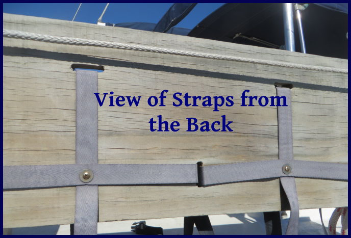
I started with two fairly large, 2”x12”x72” (50mm x 30cm x 180cm), planks. These were secured to the aft rail on each side using stainless u-bolts. Each can is then secured to the plank using two web straps - I used medium weight 1” (25mm) webbing. One strap goes around the girth of each can and one goes from top to bottom. The straps are secured on the back side of each plank with a small screw to keep them properly positioned. I like having two straps for each can. I think it is quite likely the can may slip out from under a single strap when we are on a significant heel and get hit by a wave.

fuel cans strapped on

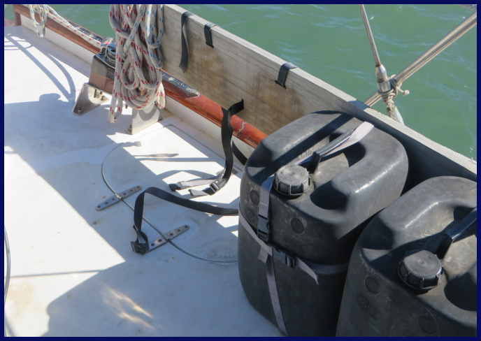
Marcie sewed buckles on the ends of the web straps, so the cans can be snapped into place and cinched tightly. Webbing expands and contracts with temperature, so I periodically check each strap for tightness.

straps from the back

Knock on wood and thanks to Neptune, we have never lost a fuel jug overboard, despite having weathered a few storms and a number of gales. It could be because of the well-designed straps – or more likely it's because we never start a passage on a Friday, always give Neptune a hearty tot of rum at the beginning and end of each passage, and never, never kill an albatross.

The Blue View - Alternative Energy Monitor

new alternative energy monitor When we bought our solar panels and wind generators about 15 years ago, we also bought a control panel and monitor to go with it. Although it was quite expensive, it seemed like a good idea at the time. It isolated and combined the inputs from up to three sources, provided a brake and “bump start” for the wind generators, and included a couple of meters to measure the voltages and amps being generated.

old alternative energy monitor

The marketing hype made it sound like it was something we wouldn't want to do without, but it didn't take long to realize we had wasted our money. The brake was ineffective in strong winds, the “bump-start” was never used, and the isolation diodes had a habit of overheating and frying (they actually melted the case on a couple of occasions). The volt and amp meters were only useful in determining whether the various inputs were still working, but when the voltmeter died a few years ago, the monitor lost even this functionality.

back of the old alt energy monitor

We now have three sources of alternative energy – solar panels, a wind generator/turbine and a generator that is attached to the prop shaft which produces power as we sail. It would be nice to have a simple monitor that would combine these three sources, and display the voltage and number of amps being generated by each source. In addition, it would be nice to keep a running total of the number of amp-hours produced by each input over the previous 24 hours.

I spent most of my working life designing microprocessor-based instrumentation, a career I enjoyed immensely, and it still remains my favorite hobby. We have our own home-brewed refrigerator/freezer controller, a windlass controller and chain counter, pump monitors, and a host of other gizmos ... some of which actually work. When I cut my teeth on microprocessor design several decades ago, it helped to have an advanced degree in electrical engineering and computer science, and required thousands of dollars in developmental tools to develop a microprocessor-based instrument. Now, the development software is often free, and I suspect the basics are taught in elementary schools. On my long list of things I planned to make when I got the chance, a replacement monitor was near the top. When I installed the new prop shaft generator, I decided to build a new alternative energy monitor.

When I was younger, processors were slower and memory was expensive, so it made sense to write software in assembly or C language, so the code would be fast and efficient. The newer processors are loaded with all kinds of hardware features, are orders of magnitude faster and memory is cheap. I have long been fond of Microchip Pic processors, and I especially like the Picaxe versions provided by Revolution Education. They are pre-programmed with download software and a Basic interpreter, making them very easy to use. All the development software is free. What might have taken me weeks or even months two decades ago, can now be done – even by an old guy like me – in days. I used a Picaxe 18m2+ processor as the core of the design.

monitor block diagram

The block diagram shows the other components. The three inputs are isolated by diodes. (Without the diodes, current can flow in both directions ... when the sun goes down, the solar panels will draw current; when the wind isn't blowing, the wind generator will become a battery-powered motor.) The voltage generated by each input is scaled down using a voltage divider and measured with an A to D converter (ADC). The current is measured with Hall effect transducers – these devices provide a voltage output proportional to the current passed through them. The display is a 4 line, 20 character, backlit LCD. Since the backlight draws a measurable amount of current, it is only turned on when the button is pressed.

As instrumentation goes, this was a pretty simple design, and I am quite happy with the end result. I tackled it in four phases – the electrical design, the software design, the mechanical fabrication and the aesthetics. For those of you who are interested in building your own monitor, I am happy to provide the design details of the project – just send us an email requesting them.

Note from the editor: This is a pretty slick device, but please note that the Captain already had all of these components (backlit display, Hall effect transducers, diodes, Picaxe processors, etc.) aboard. In fact, there's an entire drawer (plus more) dedicated to electronic components alone. So, when I bring a few extra pieces of cloth or a couple shells aboard?  Just sayin' …

Note from the Captain: Well yeah – but the electronic components are essential ship stuff and very important. Sea shells???

The Blue View - Prop Shaft Generator pt. 2

shaft generator installed Design Considerations - Mechanical

Pulley sizes. The faster the generator spins, the more current it will generate. The ratio of the two pulley sizes determines how fast the generator will spin, which in turn determines how much current will be generated. To generate the maximum current, we want a very large pulley on the shaft and a very small pulley on the generator. On the other hand, when the engine is cranked on and we are motoring, the shaft will turn much faster than when we are sailing, potentially destroying the generator if it spins too fast. On Nine of Cups, taking max engine speed, transmission ratio, and the maximum generator speed into account, the largest pulley ratio I could use is 7:1 … i.e. ideally, the diameter of the shaft pulley should be just slightly less than seven times the diameter of the generator pulley. The closest I could come to this with the parts available locally was a 4.2:1 ratio.

shaft gen pulleys

Mounting

The bracket should allow the generator to be rotated towards the shaft so that the belt can be installed/removed, then tensioned. I made some sketches and worked with a local machinist to fabricate the bracket.

Design Considerations - Electrical

Converting to DC. The output of the generator is a three phase AC voltage which must be converted to DC in order to charge the batteries. This requires six rectifier diodes connected as shown in the sketch below. Most alternators have these diodes built into them, but in our brushless DC generator/alternator hybrid, the diodes are external. The diodes should be chosen to ensure they can handle the maximum output voltage and current of the generator. I used Vishay 95PF80 diodes.

diodes sketch

Regulating the output. If the generator is spinning, it will be generating a current. If the batteries are charged, this current must be disconnected from the batteries to prevent them from being overcharged. One way to do this is to use a regulator that diverts the current into a dummy load when the batteries reach their charged state. Many companies that sell wind generators and solar panels also provide these charge controllers. We use the water heater as the dummy load.

Protecting the diodes and generator. When the engine is running and in gear, the generator RPMs will be much higher than when sailing. The open circuit voltage will reach several hundred volts, and the current when the load is diverted to the dummy load may overheat the generator. I added relays to the output of the generator to disconnect it when the engine is turned on. The complete circuit sketch, which includes the relays and charge regulator is shown below.

circuit sketch

Measured output

I completed the project in Cape Town, and it was in use during our passage to Lüderitz. Something I plan to do during our Atlantic crossing is to quantify how many amps it produces at different speeds (our bottom needs a cleaning after being in Cape Town, making the speed transducer a bit sluggish, so we couldn't measure our speed through the water). The generator output varied from 2 to 8 amps, however, and not only did we not have to start the engine, we actually shut the wind generator down at times to save wear and tear on it, as we were producing more than we needed.

A side effect is that both the spinning prop shaft and the generator produce noise when we are sailing. After a few hours, though, the hum of the prop shaft and the whine of the generator  soon become part of all the other background sounds  - creaks, groans, squeaks, chirps -  as Nine of Cups sails along, noticeable only when something changes. So far, that has been the only negative, and I regret not doing the project years ago.