The Blue View - A DIY HF Antenna

Probably 95% of the offshore sailboats we see that have either a marine or HAM radio use a long-line type antenna. This is simply a wire that runs from just above the deck to the top of the mast, with insulators at each end to electrically isolate the wire from the other metal parts of the boat. While there are a few subtleties to be considered, the antenna itself is quite simple. In this blog, I'll describe how we built a simple, inexpensive antenna. The wire is actually only half of the antenna. The other half consists of a ground plane or counterpoise. On a land based antenna, the earth is sometimes used as the ground plane, but often a network of wires is run radially out from the base of the antenna, and this type of ground system is called a counterpoise. On a boat, the seawater acts as a great ground plane as long as there is a good connection between the antenna ground and the water. In next week's blog, I'll talk about options for the ground plane/counterpoise design, and what we used.

Finally, in the third part of this series of blogs, I'll talk about other antenna options. I know – it doesn't get much more exciting than this, but please try to control your enthusiasm.

First, a caveat. While I am an electrical engineer, my expertise is not in radio electronics. (Actually, I'm not sure where my expertise lies, but I know it's not antenna design). I understand the basics, but there are a lot of other websites and blogs that were written by people far more knowledgeable on the subject than me, and I've provided links to a few of these at the end of this blog. What I plan to accomplish here is to describe an inexpensive design that works for us on Nine of Cups.

overview

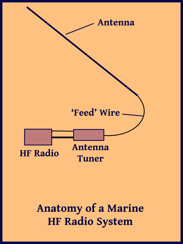
The sketch shows an overview of the radio system. The signal from the radio first passes through an antenna tuner. If we were only planning to transmit at a single frequency, we could adjust the length of the antenna to optimize it for that frequency. When we change frequencies, however, a mismatch between the radio and the antenna occurs, resulting in power being reflected back into the radio instead being transmitted. If the mismatch is big enough, the radio will actually be damaged. The tuner uses variable inductors and capacitors that are switched into and out of the circuit to match the radio output impedance to the antenna's input impedance, thus protecting the radio from the reflected radio waves. A common misconception is that the tuner 'tunes' the antenna to improve its performance at different frequencies. In actuality, the same mismatch and power losses still exist, only now it is between the tuner and the antenna. A good tuner will be able to withstand a large reflected wave and still protect the radio.

The radio connects to the automatic antenna tuner via two cables. One is a coaxial cable that carries the radio waves. The other cable provides power and control signals for the tuner. With our Icom radio, whenever the transmit frequency is changed, the radio sends a command to the automatic antenna tuner, and it matches the radio and tuner to the new frequency.

The output of the tuner is connected to the antenna via an insulated, single conductor wire. (I'll call it a feed line for simplicity, but it is actually part of the antenna system rather than a feed line.) It should be kept as short as possible. I mounted our tuner in a locker in the aft cabin to put it as close as possible to the actual antenna. The 'feed line' should be separated from any grounded metal like stanchions. I used small, 3” PVC tubing as separators.

spacer

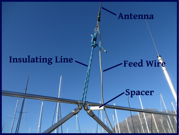
The antenna itself is a single, dedicated wire that runs from above the stern to the top of the mast. Over the years I've used uninsulated galvanized wire, electrical wire and even lifeline wire for our various antennas. Anything larger than about AWG8 wire is probably large enough as long as it is strong enough to be strung to the mast head and tensioned, and is able to withstand the occasional errant halyard. I spliced a loop into both ends of the wire using small hose clamps.

connection

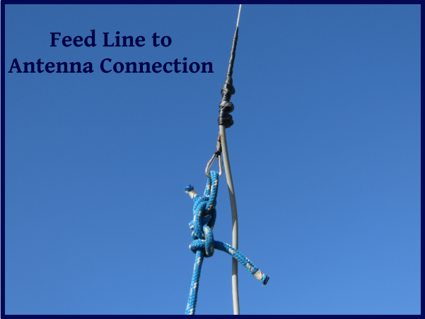
To connect the feed line to the antenna, I stripped several inches of insulation from the end of the feed wire and if the antenna I was using had an insulating cover, I removed several inches of insulation from it as well, just above the loop in the end. I wrapped the feed line around the antenna wire, secured it in place using cable ties, then weatherproofed the connection with amalgamating tape. Riggers' tape also works well.

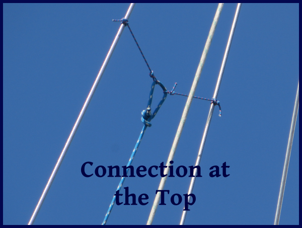
I insulated the ends of the antenna from the connections at either end using short lengths of line. Nine of Cups has a double backstay, so I attached the antenna to both backstays near the top. The bottom was attached with line to the pole supporting our windgen. If we had a single backstay, I would have attached the top to a tang on the mast, and the bottom of the antenna to the stern on either the port or starboard side, ensuring that it would always clear the mainsail.

connection at top


connection at top

Stay tuned for Part 2 in next week's Blue View.

Links:

Antenna Tuner

Antennas


The Blue View - HF Radios on the Cheap

In this day and age, almost every offshore cruising boat we encounter has the capability of long distance communications at sea. While more and more boats have both satellite transceivers and high frequency (HF) radios aboard, because of the upfront and ongoing costs, most of us have to choose one or the other. Both have their pros and cons, and when we started cruising, the cost/benefit ratio definitely favored the HF radio. Now, however, with the costs of satellite communications dropping and the reliability improving, the decision is not so clear cut. For us, the much lower operating expenses and the ability to participate in radio nets were the deciding factors, and if we were starting out again today, I think we would still opt for an HF radio. The upfront expenses of a complete HF radio system can be quite high. Installing a quality radio and all the components it takes to get the system up and running can easily cost more than $5000! We installed our system for far less than that. Here are some of the ways we used to save money without compromising quality.

hf radio components

The heart of an HF radio setup is the radio transceiver. We opted to go with an Icom IC-706MKIIG HAM radio for a couple of reasons. It was considerably less expensive than the typical marine radio, and it allowed us to communicate on the HAM radio frequencies, as well as the marine channels. It has a maximum transmission power of 100 watts vs. the 200 watts of most marine transceivers, but this hasn't been a problem. The 706 is no longer available, but the newer Icom 718 will work just as well. The cost of the 718 is $600 versus $1850 for an Icom M802 marine radio. There are a few compromises to be made, however. The biggest is that since the Icom 718 is essentially a HAM radio, the assumption is that the operator is more knowledgeable – more of a geek – than the typical marine radio operator, and the radio isn't as straightforward to program and operate. In addition, while the radio operates on both the HAM and marine frequencies, the operator must have a HAM license to transmit on the amateur radio frequencies.

icom 718

Since we use our radio for sending and receiving emails and text weather reports as well as voice communications, we needed a way to connect our computer to the radio. This was done with a PACTOR modem. We chose an SCS PTC-IIIusb modem. The newer Pactor DR-7400 transmits and receives at twice the speed and is a few hundred dollars more. The older unit works fine, but I would opt for the faster model if I was starting from scratch. Expect to pay about $1700 for the modem and all the cables.

pactor modem

If we always transmitted at the same frequency, we could tune our antenna length to that frequency and simplify the system, but since we transmit at a number of different frequencies, we need an antenna tuner in the system. We use an Icom AH-4 tuner that works as well as some of the more expensive marine models. The cost for an AH-4 tuner is around $225 while the marine version, the AT-140, costs about $450.

The next component is the antenna. Most boats use the backstay as a single long line antenna. Since the backstay is usually grounded at one or both ends, for it to act as an antenna it must be electrically isolated using backstay insulators. I'm not a big fan of this approach. One reason is the cost – each insulator costs between $250 and $450 depending on the size and brand. Another reason is that we know of two boats that were dismasted when a lightning strike disintegrated a backstay insulator. Instead, we use insulated lifeline wire and have rigged an antenna that is totally separate from the backstay. The cost is much less, the performance is just as good, and we don't worry about losing our backstay in an electrical storm.

backstay insulator


antenna

So, adding everything up, the cost of our system if we were to install it today would be $2750. That would be a big hit to our budget, but it would be a lot easier to manage than the $5300 that the typical marine version would cost.

The Blue View - Using the Series Drogue

series drogue 
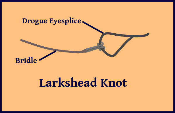
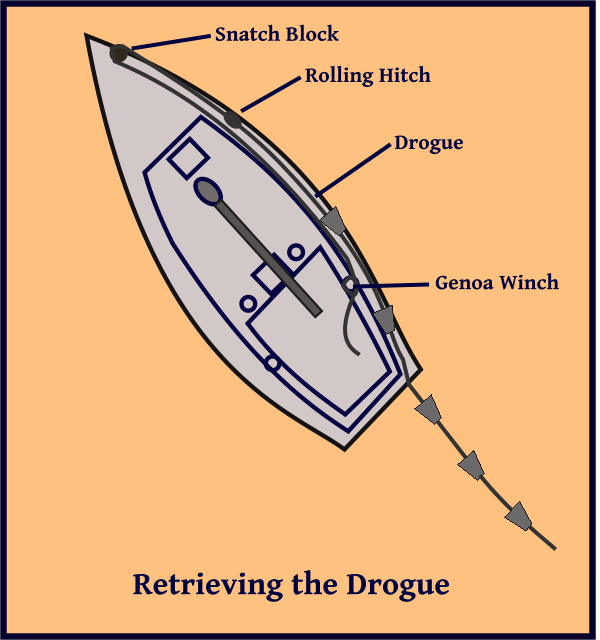
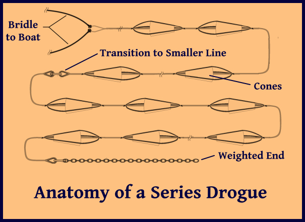
Deploying the series drogue...

Let's assume we are way offshore and the GRIBs and Buoy Weather are predicting some nasty weather coming our way. We have our trusty, handcrafted Jordan series drogue safely aboard. How are we going to deploy it?

Don Jordan recommends having the drogue bridle attached to the dedicated chainplates and the drogue flaked in a bag or container, ready for instant deployment, during any bluewater passage. It's probably good advice, but we don't normally do this. We do have it ready and accessible on a passage, however, and if the weather forecasts are indicating anything near a gale or worse, we get it prepped and ready well in advance.

To prep it, I begin by attaching the two bridle lines to the end of the drogue. Each of our bridle lines has an eyesplice in one end. Each is run through the drogue eyesplice then through its own eyesplice to form a larkshead knot around the drogue line. The drogue is positioned on the aft deck, and the other end of each bridle line is routed over the stern rail and back to the strong point on either side of our transom.

larkshead knot

Next, I connect all the drogue segments together and attach the chain we use as a weight. The drogue is then flaked out on the aft deck, starting with the bridle on the bottom and working up to the weighted end. The flaked pile is secured in place, ready to deploy.

When the weather starts getting bad, we drop and secure our sails, remove the lines securing the drogue, then drop the weight over the stern rail and let the drogue run out. Once it is properly deployed, we check that the wheel is centered, then close the hatches and go below. We make sure the AIS and radar alarms are on, then try, as best we can, to rest while we wait out the storm.

Retrieving the series drogue...

Whew – that was quite a blow! It's now two days later and we're pretty much over our seasickness. The seas are calming down, the wind has dropped to around 30 knots, and it's safe to retrieve the drogue. I use a variation of Don Jordan's method for bringing it back aboard.

I use two lines that are about twice the length of Nine of Cups – about 90 feet. I have two retired jib sheets that work well for the purpose. I rig snatch blocks to either side of the bow pulpit, then run the lines from each of the genoa winches forward to the snatch blocks and back to the stern rail. I run the port line over the rail, attach it to the starboard bridle with a rolling hitch and take the slack out of the line. Before I can start winching the drogue in, however, I have to release the bridle from the strong points on the transom. What works for me is to run the starboard line through the starboard aft hawsehole,and attach it to the bridle with a rolling hitch. Then I crank on the starboard genoa winch until the starboard bridle can be removed from its strong point on the transom. Once the bridle end is free, I slack off on the starboard line until the port line is tensioned. Next, I winch the port line in until the end of the bridle is on the aft deck. Then, I release the port bridle from its strong point, untie the starboard line from the starboard bridle, and pull it back aboard through the hawsehole.

The next steps are as follows:

  1. I winch the port line until the rolling hitch reaches the snatch block. As the drogue is winched forward, I keep an eye on it to make sure none of the cones catch on anything.
  2. Then I tie the end of the starboard line to the drogue with a rolling hitch and winch it tight enough to take the tension off the port line.
  3. Next, I release the port line from the genoa winch, walk forward, untie the rolling hitch, and bring the end of the line back to the stern rail. I also pull the portion of the drogue that lies on the port deck back to the aft deck.
  4. Finally, I winch the starboard line in until the rolling hitch reaches the snatch block.

retrieving the drogue

I repeat the process until the drogue has been retrieved. Since our bridle is about 375 feet long, I have to winch each side about four times.

I don't want to stow a wet drogue, so I flake it on the aft deck and secure it. At the next opportunity, I will separate the drogue sections, hose them off with fresh water and set them out to dry. Then I will flake and secure each section and stow them below.

The process isn't as complicated as it sounds, but it isn't something I do everyday. We might go a year or more without even thinking about the drogue, which is about 11 months longer than I need to forget most of the details. I keep sketches and notes stashed in a ziplock, which is taped to the drogue so I can refresh my memory when it comes time to deploy it.