The Blue View - Alternative Antennas
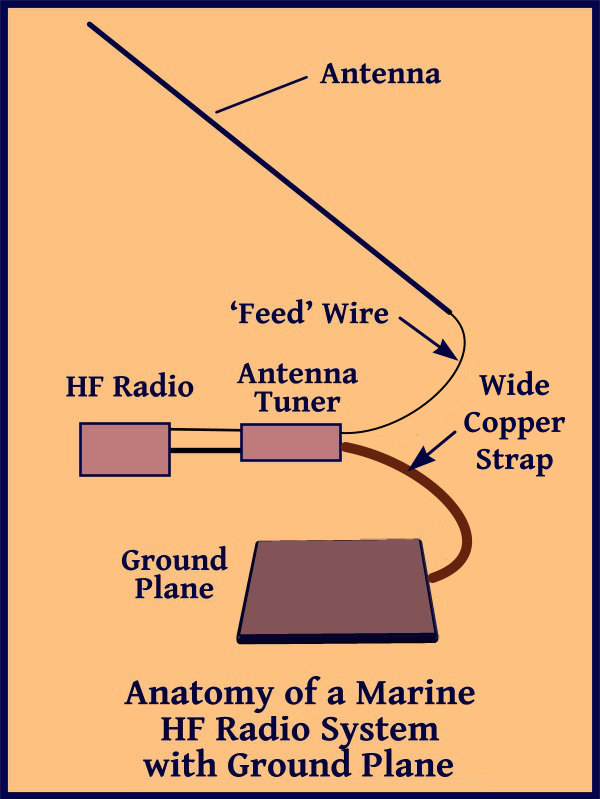
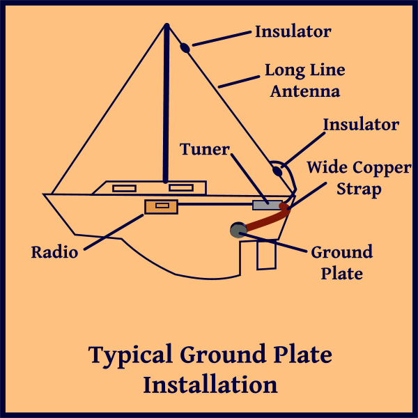
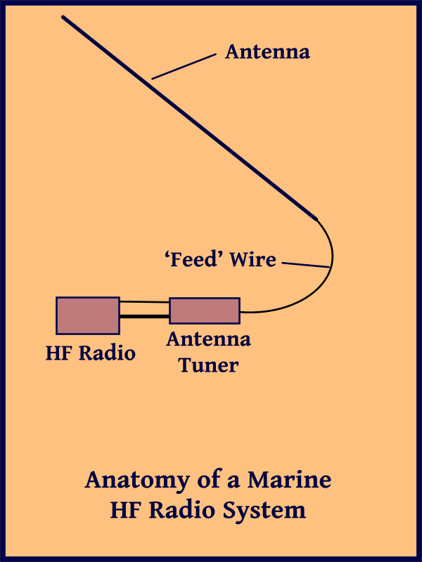
In the last Blue View, I talked about a long line antenna, which is what most cruising boats use for transmitting, either on the marine bands or on the HAM frequencies. As I mentioned, probably 95% of the cruising sailboats we see use a long line type antenna for their HF radios, but there are a couple of other alternatives. antennas

One alternative is a whip antenna. This is a 23' fiberglass antenna that is mounted to a rail, usually near the stern of a sailboat. The rail is typically used as the counterpoise. The whip antenna is more often used on power boats, but we have seen a number of sailboats using them as well. The drawbacks: they are expensive (although no more so than buying and installing a couple of backstay insulators); the mounting method must be robust as a 23' pole aboard a sailboat that is rolling in a seaway will put a lot of stress on the mounting point; the transmission range is typically less than that of a properly installed long line antenna – some estimates I've seen indicate as much as 30% less.

dipole antenna


Another alternative is a dipole antenna. A dipole antenna may be the most widely used antenna for shore-based systems. The most common version is made up of two identical length conductors placed end-to-end. The radio signal connection is made at the junction of the two wires. The dipole antenna is only resonant within a small frequency range (example: 14.0Mhz-14.5Mhz), and is tuned by adjusting the length of the two conductors. If it is operated at the tuned transmission frequency, no antenna tuner is needed – the dipole can be connected directly to the radio. We commonly transmit in the 14Mhz range, so the dipole I built was tuned for this range. I found, however, that if I connected it through my antenna tuner, it transmits reasonably well throughout the 10Mhz to 18Mhz range – maybe not quite as well as the long line, but not bad. On the other hand, within its resonant frequency band, it is superior to our long line antenna.

dipole construction

I built a rather simple version. I used coax cable from the antenna tuner to the junction of the two dipole conductors. As an insulator, I used a one foot section of 1x2 wood, and soldered the connections between the coax and the dipole conductors. Each of the conductors were secured with cable ties, and the entire insulator was wrapped in rigger's tape to protect it from the elements. I used a spare halyard to hoist one end of the antenna and secured the other end to the stern rail. The coax wire was led from the insulator to a cable tie on the backstay, then to our antenna tuner.

The length of the two dipole conductors should be 1/2 wavelength in total which, if you're not a radio geek, is determined by the formula: length in feet = 468/frequency in megahertz. So if you want to transmit at 14.2Mhz, the theoretical length of the conductors should be 468/14.2 = 32.96 feet, and each conductor should be half of this, or 16.48 feet. Note that this is the theoretical length. The optimal length will vary from the theoretical based on a host of variables – the type and length of feed line, other rigging, masts, angle of the dipole, etc.

dipole rigged

To tune the antenna length, I used my radio's built in Standing Wave Ratio (SWR) meter. I was at anchor, but if I was at a marina, I would have moved Nine of Cups to an anchorage or mooring to avoid any interference from other boats or structures. I started by making the length of the dipole conductors slightly longer than the theoretical lengths, hoisted it into position and checked the SWR. The SWR will be lowest at the resonant frequency of the dipole, and to start, the center of the resonant frequency was lower than the desired frequency of 14.2Mhz. I lowered the antenna and trimmed off an inch from each conductor, then repeated the process until the the resonant frequency was centered around 14.2Mhz.

The purists out there will know this wasn't the optimal method of building a dipole. I should have used a balun between the coax feed line and the dipole conductors, or alternatively used a twin lead feed line instead of coax. There are also ways to build a multi-frequency dipole that will transmit at three frequency ranges. This was my first attempt, however, and I wanted to keep it simple. As it turns out, I was quite happy with its performance and didn't modify it.

multi frequency dipole

If I didn't have a SWR meter, I would have made the lengths of the conductors the theoretical lengths and used an antenna tuner between the dipole and the radio. This is the configuration I use anyway, since I often use the dipole at other than the resonant frequency.

So what do we actually use? Most often we rely on our old long line antenna, and the dipole is our backup. Since it doesn't require a ground plane, I also dig it out when we are on the hard where the performance of the long line drops dramatically.

Well – to paraphrase my dear old dad – I've taught you everything I know about HF radios and antennas and you still don't know nuthin'.

Next week I'll move on to a totally new subject – stay tuned.

The Blue View - HF Radio Ground Systems

In the last Blue View, I talked about a typical marine HF radio setup, consisting of the radio, an automatic antenna tuner and a long line antenna. As I mentioned, the wire of the antenna is only half of the antenna. To transmit any distance, a good ground plane or counterpoise is also needed. On a land based antenna, the earth is sometimes used as the ground plane, but often a network of wires is run radially out from the base of the antenna, and this type of ground system is called a counterpoise. On a boat, the seawater acts as a great ground plane as long as there is a good connection between the antenna ground and the water. overview

If the boat is steel, all that needs to be done is to connect the antenna ground to the hull. I'm not sure whether the hull would be classified a counterpoise or a good ground connection. More likely, it is some of both.

On plastic or wooden boats, making a ground connection or counterpoise is slightly more complicated. One method is to attach a large ground plate to the outside of the hull under the water line. It is held in place with large bolts through the hull, then the antenna ground is connected to it using a wide copper strap.

groundplate

A variation of this is to use a copper strap to connect the ground to one or more bronze thru-hulls. This method is most effective if the thru- hull is located close to the antenna ground, ideally 3-4 feet, but a maximum of 10-15 feet, and the conductor to make the connection is a wide – 3” or more – copper strap. Gordon West, arguably the foremost expert on marine radios, is a proponent of this system.

Another method is to construct a counterpoise by running as many copper straps as possible from the antenna ground, and connecting metal tanks, lead keels and other various metal objects together. Steel lifelines, stanchions and even the mast can be included. This can be a very effective counterpoise, but it is difficult to add all that copper. In addition, since copper and seawater don't go together well, the copper should be protected from corrosion, especially anywhere that the copper strap might come in contact with seawater – like the bilge for example. Some installers encapsulate the copper straps in epoxy and bond it to the hull. We also saw one boat that had a blister problem, and was having the gel coat stripped. Before the new epoxy barrier coat was applied, they bonded a copper mesh to the hull. Unfortunately, we didn't keep in touch with the owners, so we don't know how well the counterpoise worked nor whether there were any long term bonding problems.

counterpoise

A third method is a commercial product, the KISS_SSB, that uses a number of wires of various lengths bundled together and connected to the antenna. The wires are all contained in a flexible tube about the size of a garden hose. The manufacturer claims that the various lengths of wire are finely tuned to make sure the radio transmits well on all the marine and HAM frequencies between 2Mhz and 28 Mhz. It is somewhat costly ~$150, but very easy to install. A heavy wire is used to connect the wires to the antenna ground, and then the bundle of wires can be routed under the cabin sole or in a lazarette locker. The manufacturer's website has lots of endorsements, and those of our friends who have installed them claim their transmission ability has improved. Other knowledgeable experts (whose opinions I respect, BTW) insist that the device can't possibly work as claimed. There are several forums devoted to the topic, resulting in a number of heated discussions between the proponents and the detractors. The only performance testing I've seen was done by John (KA4WJA) on the s/v Annie Laurie. He used a spectrum analyzer to measure the the return loss/VSWR/resonance of a transmitter equipped with the KISS-SSB counterpoise as the transmitter was swept throughout the frequency range of 1.5Mhz to 28.5Mhz. His conclusion was that it would probably work great on three or four frequencies and have a marginal performance throughout the rest of the range. His opinion: “If you just grab some wire out of a dumpster, cut it into a few random lengths (between 12' and 35'), attach a ring terminal to the end of the group of wires...you HAVE made an antenna counterpoise for FREE that works as well as (or better than) the KISS....and if you need to buy some wire, it'll cost you < $5.... “.

kiss installation

So, there is the opinion of several experts as well as John's test results saying it can't and doesn't perform as claimed by the manufacturer versus the actual real world, albeit subjective, experience of a number of actual users claiming it is great. I love it!

Meanwhile, what did we do? Sixteen years ago, when we first started cruising, I read everything I could and decided to use the second method. I bought 100 feet of 3” copper strap and connected all my fuel and water tanks together, as well as a few thru-hulls, and attached it all to the antenna ground. This has worked reasonably well for us over the years, but some segments of the copper have started to deteriorate. Nine of Cups is currently on the hard in Trinidad, and one of the items on my to-do list is to replace the thru-hull for the port cockpit drain. As long as I will be scrunched head down into the lower reaches of the engine compartment, I plan to run a copper strap directly from the antenna tuner to this thru-hull and see whether there is any improvement in our transmission range.

I'll keep you posted. Meanwhile, stay tuned for the next blog when I'll talk about alternative antennas.

The Blue View - A DIY HF Antenna

Probably 95% of the offshore sailboats we see that have either a marine or HAM radio use a long-line type antenna. This is simply a wire that runs from just above the deck to the top of the mast, with insulators at each end to electrically isolate the wire from the other metal parts of the boat. While there are a few subtleties to be considered, the antenna itself is quite simple. In this blog, I'll describe how we built a simple, inexpensive antenna. The wire is actually only half of the antenna. The other half consists of a ground plane or counterpoise. On a land based antenna, the earth is sometimes used as the ground plane, but often a network of wires is run radially out from the base of the antenna, and this type of ground system is called a counterpoise. On a boat, the seawater acts as a great ground plane as long as there is a good connection between the antenna ground and the water. In next week's blog, I'll talk about options for the ground plane/counterpoise design, and what we used.

Finally, in the third part of this series of blogs, I'll talk about other antenna options. I know – it doesn't get much more exciting than this, but please try to control your enthusiasm.

First, a caveat. While I am an electrical engineer, my expertise is not in radio electronics. (Actually, I'm not sure where my expertise lies, but I know it's not antenna design). I understand the basics, but there are a lot of other websites and blogs that were written by people far more knowledgeable on the subject than me, and I've provided links to a few of these at the end of this blog. What I plan to accomplish here is to describe an inexpensive design that works for us on Nine of Cups.

overview

The sketch shows an overview of the radio system. The signal from the radio first passes through an antenna tuner. If we were only planning to transmit at a single frequency, we could adjust the length of the antenna to optimize it for that frequency. When we change frequencies, however, a mismatch between the radio and the antenna occurs, resulting in power being reflected back into the radio instead being transmitted. If the mismatch is big enough, the radio will actually be damaged. The tuner uses variable inductors and capacitors that are switched into and out of the circuit to match the radio output impedance to the antenna's input impedance, thus protecting the radio from the reflected radio waves. A common misconception is that the tuner 'tunes' the antenna to improve its performance at different frequencies. In actuality, the same mismatch and power losses still exist, only now it is between the tuner and the antenna. A good tuner will be able to withstand a large reflected wave and still protect the radio.

The radio connects to the automatic antenna tuner via two cables. One is a coaxial cable that carries the radio waves. The other cable provides power and control signals for the tuner. With our Icom radio, whenever the transmit frequency is changed, the radio sends a command to the automatic antenna tuner, and it matches the radio and tuner to the new frequency.

The output of the tuner is connected to the antenna via an insulated, single conductor wire. (I'll call it a feed line for simplicity, but it is actually part of the antenna system rather than a feed line.) It should be kept as short as possible. I mounted our tuner in a locker in the aft cabin to put it as close as possible to the actual antenna. The 'feed line' should be separated from any grounded metal like stanchions. I used small, 3” PVC tubing as separators.

spacer

The antenna itself is a single, dedicated wire that runs from above the stern to the top of the mast. Over the years I've used uninsulated galvanized wire, electrical wire and even lifeline wire for our various antennas. Anything larger than about AWG8 wire is probably large enough as long as it is strong enough to be strung to the mast head and tensioned, and is able to withstand the occasional errant halyard. I spliced a loop into both ends of the wire using small hose clamps.

connection

To connect the feed line to the antenna, I stripped several inches of insulation from the end of the feed wire and if the antenna I was using had an insulating cover, I removed several inches of insulation from it as well, just above the loop in the end. I wrapped the feed line around the antenna wire, secured it in place using cable ties, then weatherproofed the connection with amalgamating tape. Riggers' tape also works well.

I insulated the ends of the antenna from the connections at either end using short lengths of line. Nine of Cups has a double backstay, so I attached the antenna to both backstays near the top. The bottom was attached with line to the pole supporting our windgen. If we had a single backstay, I would have attached the top to a tang on the mast, and the bottom of the antenna to the stern on either the port or starboard side, ensuring that it would always clear the mainsail.

connection at top


connection at top

Stay tuned for Part 2 in next week's Blue View.

Links:

Antenna Tuner

Antennas