The Blue View - Windlass Chain Counter

  windlass chain counter

In the last two Blue Views, I talked about our experience with windlass controllers – what worked for us and what didn't and our own version of a handheld controller. In this Blue View, I want to show you how to make a digital chain counter.

The chain counter keeps track of the revolutions of the windlass gypsy, calculates exactly how much chain or rope is deployed, and displays the result in feet or meters on a small LED display. It uses very little power, drawing a few hundred milliamps when operating and only a few milliamps when it's not being used.

I know, I know – if you've never sailed, you probably couldn't care less. If you're an old salt, you're probably thinking “why don't you just mark the chain, ya idgit?”. Well, we do mark the chain, and use the marks as our backup system. We've actually used three different methods to accomplish the job - I talk about the different methods we've used in my book Nine of Cups Guide to Anchors and Anchoring.

I could argue that there are times when the marks are difficult to see, like when the chain is coated in mud or it's a dark and gloomy night - both of which are true. I could also argue that after we are hooked and I go forward to attach the snubber, it's nice to be able to double check, at a glance, that how much chain I think Marcie deployed is actually what's in the water. Probably the biggest reason I built my chain counter, if truth be told however, is that I'm a geek and just really enjoy these projects. Marcie is quite patient as I explain how much easier her job will be and that I'm doing this just for her – or that I can't imagine how we've managed to cruise all these years without whatever I'm planning to build.

The first issue to resolve is how to keep track of the windlass revolutions. If a magnet is passed in close proximity to a magnetic reed switch, the magnetic pull causes the switch contacts to close. By attaching the magnet to the bottom of the windlass gypsy, and attaching the reed switch to the deck or the base of the windlass just below the gypsy, each rotation of the gypsy will pass the magnet over the reed switch, closing its contacts for a few milliseconds.

chain counter rotation sensor

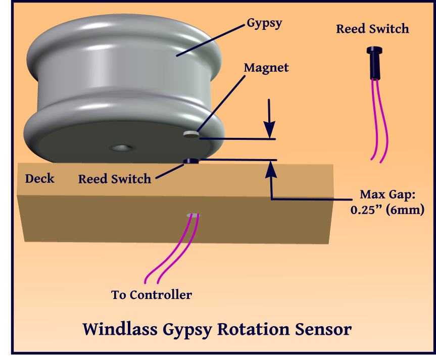
On our old Maxwell windlass, I had to drill a small indentation in the gypsy bottom in which to mount the magnet. I used Sika bedding compound to hold it in place and seal it from the elements. On our newer Lofrans windlass, a magnet sized dimple just the right size for a magnet was already part of the design. When we replaced the windlass last year, the gypsy came with a magnet already bonded in place.

The reed switch is mounted either in the deck or in the base of the windlass. The maximum gap between the magnet and the reed switch should be about 0.25” (6mm). The Lofrans windlass has a pre-drilled hole in the base that is intended for a reed switch, so all that is necessary is to drill a hole in the deck to pass the wiring through. As with any hole in the deck, the core should be sealed with epoxy to prevent damage. Once the switch and wiring are in place, the entire hole can be sealed with silicone.

chain counter block diagram

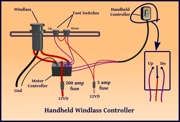
The block diagram shows the general design. The handheld enclosure has two pushbutton switches which, when pushed, connect 12 vdc to the 'Up' or the 'Down' terminals of the windlass motor controller. The reed switch contacts are connected to one of the microcontroller input pins. The microcontroller knows that each time the reed switch contacts close, the gypsy has made one revolution, and from this, can calculate how many feet or meters of rode have been deployed. Since the microcontroller cannot tell which way the gypsy is rotating, it also checks whether the 'Up' button is being pushed. If the gypsy is rotating and the 'Up' button is depressed, the chain is being retrieved. If the gypsy is rotating and the 'Up' button is not depressed, the chain must be going out.

The display is a three digit, 8 segment LED display. Since the LEDs draw a measurable amount of current, the display is turned off when the windlass has not been operated for about five minutes.

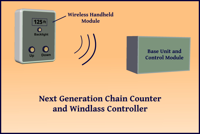
All in all, this was a pretty simple design, and we have been using it for about four years now. Generally, I am happy with it, but I plan to do a couple of things differently in the next version. First, the LED display in the current version is quite bright in low ambient light, but hard to read in bright sunlight. I will replace it with a backlit, daylight readable LCD display which should make it more visible in either the bright sun or at night. Also, with all the new technology now available, I plan to make the handheld module wireless and battery-powered, eliminating the cable. It should be pretty straightforward to incorporate matching 90mhz – 2.4 ghz radio transceivers in the handheld module and in the control module mounted in the forepeak locker.

next generation chain counter

For those of you who are interested in building your own windlass controller and chain counter, I am happy to provide the design details for the current version – just send us an email requesting them. Alternatively, if you aren't in a hurry, I plan to build the next version during the first few months of 2016, and should have all the design details available soon after. (I'd start working on it now, but I can't seem to find the right LCD display and RF Transceivers at the hardware store here in Bartica, Guyana – go figure.)

The Blue View - Handheld Windlass Controller

anchored off bartica In the last Blue View, Nine of Cups was in Suriname and I talked about installing foot switches for controlling a windlass, and using a windlass motor control module to reduce the current that passes through the switch contacts. Now we are 50 miles up the Essequibo River in Guyana, anchored off the small town of Bartica. In this BV, I want to address the usefulness of a handheld windlass controller and how to make one.

up the essequibo

Navigating the river was a challenge at times. The river has a strong tidal current, and it is necessary to wait until the current is flowing in the right direction before heading upriver. I know this is nothing new to you sailors who grew up sailing in waters with a large tidal swing, but for a guy who grew up in Colorado, it never ceases to amaze me when a river not only flows backwards six out of every twelve hours, but does so with great enthusiasm. The river is quite muddy, making it impossible to pick out shoals and rocks visually. In addition, the electronic charts are off by several hundred feet, and most of the channel markers have long since disappeared. Finally, the local fishermen use long nets, either stretched between poles stuck in the river or between an anchored float and their small dugout fishing boats. Our trip up the river had to correspond to the tidal swings, but had to be in daylight as well. We anchored offshore the first night, a few miles up the river on the second night, and made it to Bartica during the flood tide on the following day.

hosing off the chain

The river is quite muddy, and every time we haul the anchor, it and the chain come up coated with thick grey mud and clay. Our Boss anchor pulls up great gooey globs of the stuff. Rather than getting the mud all over the deck and down into the chain locker, Marcie uses the deck wash and hose to wash the mud off as the chain comes up. She leans over the bow pulpit, raises the anchor a few feet, and sprays the exposed chain until the mud is washed off, then repeats the process. Unfortunately, in this position, she can't reach the windlass foot switch with her toe.

hand held controller

Our handheld windlass controller makes her job easier and faster. She can lean over the bow pulpit with the hose sprayer in one hand, while controlling the windlass with the other. When we have a lot of chain out and the mud is thick, raising the anchor might take a half hour using the foot switches, while the handheld controller might knock ten minutes off the process. Notice that we still have the foot switches mounted in the deck. If either the foot switch or the handheld controller stops working, the other remains as a backup.

hand held controller sketch

The handheld controller is nothing more than a SPDT rocker switch mounted in a small palm-sized enclosure and connected to the windlass motor control module with a long, three conductor cable. The cable is long enough to reach from the motor controller to the bow. One switch contact connects 12vdc to the 'Up' connection on the motor control module and the other contact connects 12vdc to the 'Down' connection. Since the current required for these connections is less than 5 amps,(typically 3 amps) for our Lofrans windlass motor control module, the switches and wiring can both be small. I used a waterproof Cole Hersee “Contura” rocker switch from West Marine (C-H Pt. No. 58332-22-BP). I store the handheld controller in a small bin mounted in the forepeak locker when not in use to keep it out of the elements for most of its life.

In the next Blue View, I'll talk about our chain counter. It's not difficult to add a small display and some circuitry to the handheld controller so that Marcie can see how much chain is in the water as we drop or raise anchor. Marcie may disagree, but for you fellow sailor-geeks out there, it just doesn't get much more entertaining than that.

The Blue View - Windlass Controllers

windlass foot switch As I write this, we are in Suriname, moored near the tiny town of Domburg. A couple of nights ago, an American catamaran sailed in after a passage from Brazil. When they tried to anchor, their windlass jammed with the anchor partially deployed. They had just enough rode out to snag on the bottom, but not enough to hold the boat in place. As they tried to fix the problem, they ended up hitting another boat, then getting thoroughly entangled with it. After a bit of spirited language and a few hours of work, they were finally able to get clear of the other boat and anchor. There were a few rookie mistakes involved, but I shan't pass any judgments – Lordy, we've certainly made our share of mistakes along the way.

It did, however, remind me of the love-hate relationship we have with our windlass, that big, fat hunk of metal that raises and lowers the anchor. With the size of our anchor and the amount of chain we use, it is a very important piece of gear, and something we depend on. When it is working, we love it, but it's a royal pain when it isn't.

In a calm, flat anchorage, I might still be able to haul in a couple hundred pounds of dead weight by hand (I see Marcie smirking about this claim), but it would be a struggle. An alternative would be to use a line attached to a cockpit winch, and winch the chain onto the deck, 25 feet at a time. It would be slow and messy, but the winch would get the job done. When conditions change, however, and we need to leave in a hurry, a working windlass on Nine of Cups becomes essential. We both remember trying to leave a deep anchorage at Tristan de Cunha when the wind shifted and the anchorage became untenable. We were taking waves over the bow and when our venerable old windlass crapped out, Marcie struggled to keep us off the rocks while I hauled in all 250 feet (75m) of chain and our 110 lb. (50kg) anchor. It took hours. Not something I'd want to do on a routine basis.

I've devoted a couple of blogs to windlasses and how we replaced ours. Just as important is the windlass controller. The windlass isn't much good if the switches that operate it aren't reliable. We've tried several different methods, some of which worked well and some of which didn't.

windlass control option 1

When we bought Nine of Cups, she had a heavy-duty Maxwell windlass that was operated by two deck mounted foot switches. The system was simple and straightforward – when you stepped on one of the foot switches, the contacts of the switch connected the 12 VDC to the windlass motor. This approach, while simple, had two problems.

The first problem was the 150 amps of current that passed through the switch contacts. In the salty environment in which the switches live, conducting that much current through the switch contacts caused a lot of arcing, which in turn, caused the contacts to pit and deteriorate. I think I replaced those switches once a year for the first three years we owned Cups before I got wise to the problem.

windlass control option 2

In the next iteration, I used a windlass motor control module. In this option, only a relatively small 3-5 amps of current passes through the foot switches, and the solid state relays of the motor controller handle the 150 amps required by the windlass. The foot switches now last many years instead of just one.

The second problem was damage to the deck core from water ingress. Whoever originally installed the deck switches did nothing to protect the core except caulk under the foot switches. Eventually, water made its way into the core, causing the core to deteriorate and the bond between the core and deck to weaken. When we were in New Zealand a few years ago, I removed the top of the foredeck, replaced the wet, damaged core, epoxied it and the deck back together, then fared and repainted the whole area. The job turned out well, and is probably stronger than when new, but it was a lot of work. It would have been a lot easier to prevent the damage to begin with.

windlass control fastener

Any time I drill a hole in the deck, I do what I can to protect the core from water damage. If I am using self tapping screws, I first drill a hole in the proper location. The hole should be the proper size for the screw and slightly longer than the screw length. Then I increase the hole size by .25” (6mm), about 75% of the depth that the screw will penetrate the core. I will want to remove the screw and fitting later, so I coat both with wax or silicone grease. Then I use a Q-tip to paint the inside of the hole with epoxy. As it is kicking, I mix a batch of thickened epoxy, about the consistency of ketchup, and pour it into the hole. Then I position the fitting and screw the fastener in place. I use just enough pressure to hold the fitting in place. Once the epoxy has cured, I remove the parts, caulk underneath the fitting, and screw it back in place, tightening the screws enough to make a good seal, but not enough to squeeze all the caulk out from under the fitting.

switchfoot epoxy

Any hole that penetrates the bottom layer of the deck, like the hole for the foot switch for example, should be temporarily sealed from the bottom to prevent the epoxy from dripping down into the interior. If it is a small hole, I make a plug from modeling clay. If it is a large hole, I attach a piece of scrap plywood to the underside of the deck using a glue gun. I use only enough to tack the wood in place, so it's not too difficult to remove later. Then I seal any gaps between the plywood and the lower surface of the deck with modeling clay. Next, I paint the core with epoxy to wet it out, and give it a coat of thickened epoxy. In this case, the epoxy should be thicker – maybe the consistency of peanut butter, to keep it from sagging too much.

All this sounds like a lot of work, but the hour you spend now will save a few weeks work repairing a spongy deck core down the road.

Stay tuned – in the next blog I'll talk about making a handheld windlass controller, and, if you aren't too “windlass controller-ed” out by then, I'll show you my nifty digital chain counter.

Marcie's comment: “Geek sailors of the world unite!”